Method of burnishing a burnishable rear pad slider in a disk drive

a rear pad slider and disk drive technology, applied in the direction of information storage, magnetic recording, maintaining head carrier alignment, etc., can solve the problem of less than aerodynamic optimal shape, and achieve the effect of enhancing burnishment, fast, and inexpensiv

Inactive Publication Date: 2005-05-24
HITACHI GLOBAL STORAGE TECH NETHERLANDS BV
View PDF17 Cites 2 Cited by
  • Summary
  • Abstract
  • Description
  • Claims
  • Application Information

AI Technical Summary

Benefits of technology

[0009]One aspect of the present invention relates to a method of burnishing a rear pad of a slider within a disk drive. The rear pad is formed of a burnishable material and maintains a read and / or write element. The disk drive further includes a spindle motor rotatably driving a disk, and an actuator assembly positioning the slider over a surface of the disk. With this in mind, the method includes rotating the disk. The slider is moved in a radial fashion relative to the disk surface in a reciprocal fashion, causing the rear pad to rock. As the rear pad rocks, contact between the rear pad and the disk surface burnishes the rear pad. As a result, a positive camber is imparted in the rear pad relative to the read and / or write element. The above-described method can be practiced following initial manufacture of the disk drive, or at various times over the life of the disk drive. Regardless, the method is practiced in-situ and is therefore very fast, inexpensive, and adapts quickly to the particular disk surface over which the slider is flying.
[0010]Another aspect of the present invention relates to a method of shaping a rear pad of a slider within a disk drive. The rear pad is formed of a burnishable material and maintains a read and / or write element. The disk drive further includes a spindle motor rotatably driving a disk and an actuator assembly positioning the slider over a surface of the disk. Further, during normal operation of the disk drive, rotation of the disk at a normal operational speed generates an air bearing between the slider and the disk surface, the air bearing dictating a fly height. With this in mind, the method includes initially forming the rear pad to an increased height such that at the normal operational speed, the rear pad is loaded against the disk surface and the fly height is zero. The disk is rotated such that the rear pad rubs against the disk surface. Finally, the slider is maneuvered radially relative to the disk surface in a reciprocal fashion as part of a first burnishing mode of operation, causing the rear pad to rock. During a first burnishing mode of operation, the above-described contact between the rear pad and the disk surface causes the height of the rear pad to decrease and imparts a positive camber into the rear pad. In one preferred embodiment, the method further includes establishing a radial acceleration of the slider in the first burnishing mode of operation as greater than a radial acceleration of the slider under normal operational conditions of the disk drive. In another preferred embodiment, the disk rotational speed is varied to further enhance burnishment.

Problems solved by technology

For disk drive applications, this shape is less than aerodynamically optimal.

Method used


Image

  • Method of burnishing a burnishable rear pad slider in a disk drive
  • Method of burnishing a burnishable rear pad slider in a disk drive
  • Method of burnishing a burnishable rear pad slider in a disk drive

Examples


Embodiment Construction

[0015]In the following detailed description of the preferred embodiments, reference is made to the accompanying drawings which form a part hereof, and in which is shown by way of illustration specific embodiments in which the invention may be practiced. It is to be understood that other embodiments may be utilized and structural or logical changes may be made without departing from the scope of the present invention. The following detailed description, therefore, is not to be taken in a limiting sense, and the scope of the present invention is defined by the appended claims.

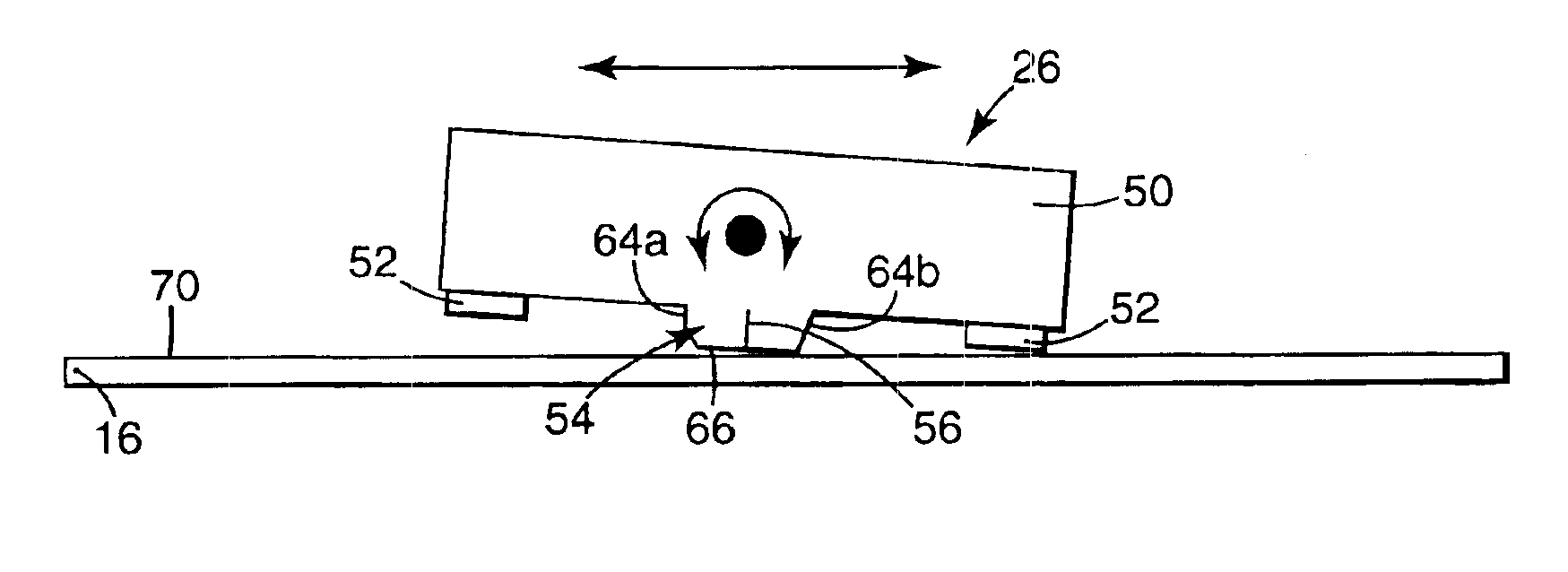
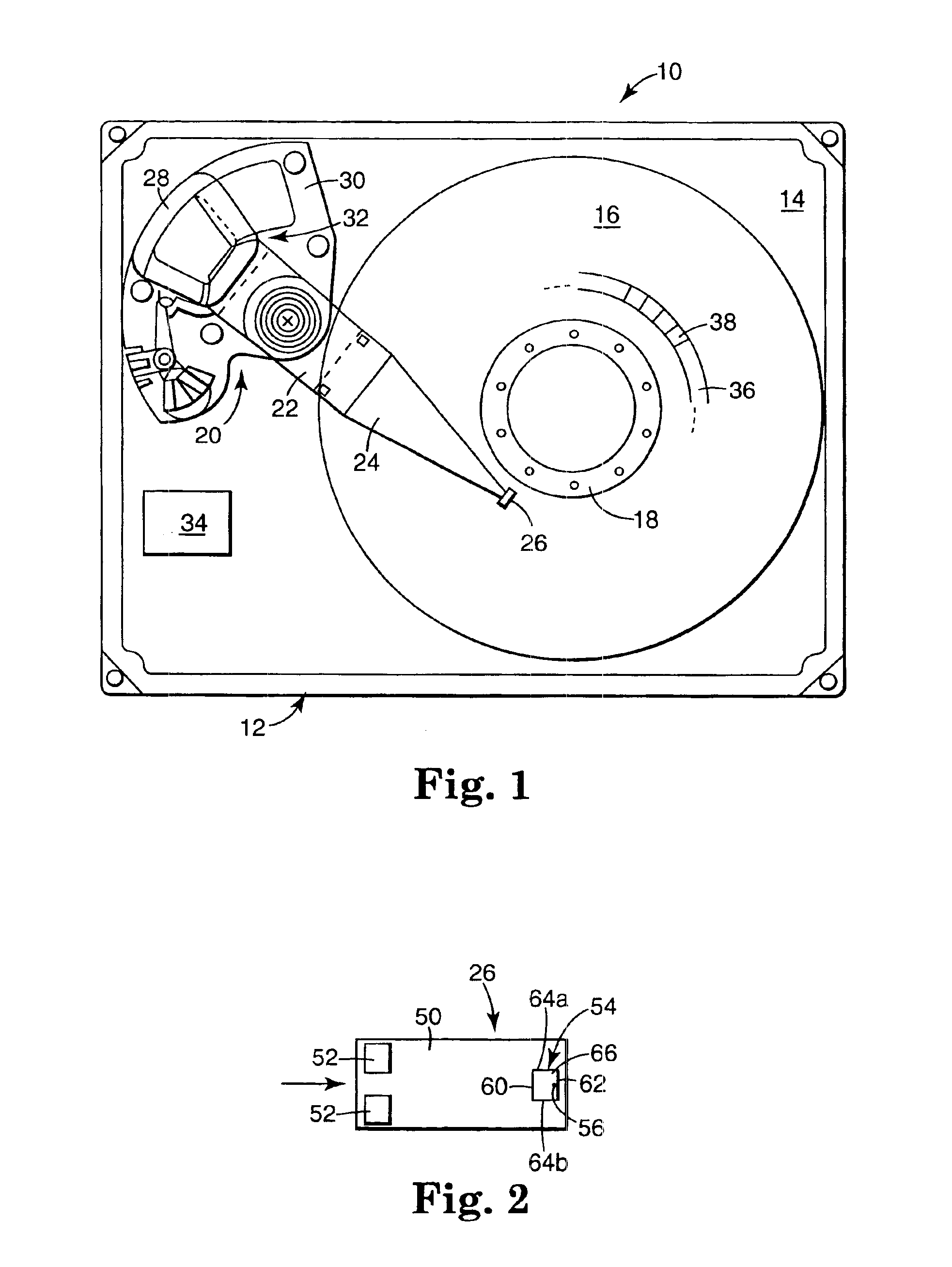
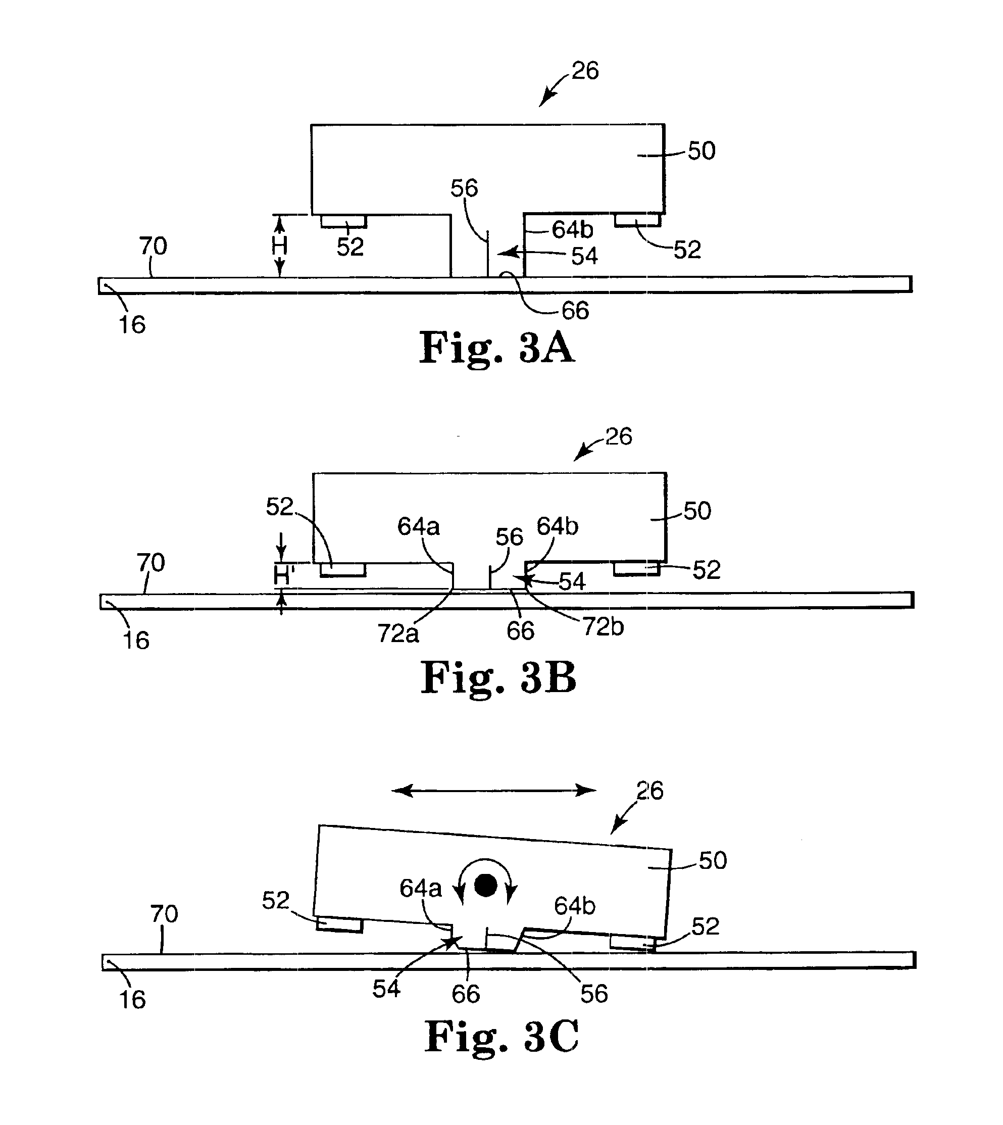
[0016]An exemplary disk drive system 10 is provided in FIG. 1. As a point of reference, the disk drive 10 includes a housing 12 defined by a cover (not shown) and a base 14. For ease of illustration, the cover has been removed from the view of FIG. 1. As a further point of reference, the disk drive 10 is shown by way of example and not of limitation. Many different types of disk drive data storage devices or syst...


PUM

PropertyMeasurementUnit
heightaaaaaaaaaa
camberaaaaaaaaaa
heightaaaaaaaaaa

Abstract

A method of burnishing a rear pad of a slider within a disk drive. The rear pad is formed of a burnishable material and maintains elements for reading and writing. The disk drive further includes a spindle motor rotatably driving a disk and an actuator assembly positioning the slider over a surface of the disk. With this in mind, the method includes rotating the disk. The slider is moved in a radial fashion relative to the disk surface in a reciprocal fashion, causing the rear pad to rock. As the rear pad rocks, contact between the rear pad and the disk surface burnishes the rear pad. As a result, a positive camber is imparted in the rear pad relative to the MR element. The above-described method can be practiced following initial manufacture of the disk drive, or at various times over the life of the disk drive. Regardless, the method is practiced in-situ and is therefore very fast, cheap, and adapts quickly to the particular disk in which the slider is flying.

Description

[0001]This application is a continuation of Ser. No. 09 / 886,566 filed Jun. 21, 2001.FIELD OF THE INVENTION[0002]The present invention relates to air bearing sliders for use with disk drives. More particularly, it relates to a method of forming or burnishing a burnishable rear pad slider within a disk drive.BACKGROUND OF THE INVENTION[0003]A magnetic disk drive apparatus is an apparatus for recording and reading data on the surfaces of spinning disks through the use of a changing magnetic field. One or more data storage disks are coaxially mounted on a hub of a spindle motor. The spindle motor rotates the disks at speeds typically on the order of several thousand to tens of thousands of revolutions-per-minute. Digital information, representing various types of data, is typically written to and read from the data storage disks by one or more transducers, or read / write heads, which are mounted to an actuator assembly and hover above the surface of the rapidly rotating disks.[0004]The t...

Claims


Application Information

Patent Timeline
Patent Type & Authority Patents(United States)
IPC IPC(8): B24B1/00B24B39/00B24B39/06G11B5/60
CPCB24B1/00G11B5/60B24B39/06Y10T29/47
Inventor SMITH, GORDON JAMES
Owner HITACHI GLOBAL STORAGE TECH NETHERLANDS BV
Why Eureka
Try Eureka