Mail sorter

a sorter and mail technology, applied in sorting, membrane technology, instruments, etc., can solve the problems of limited space for providing mail sorting lines, restrictions on the design of lines, and inability to provide mail sorting lines near buildings, so as to avoid damage and recovery errors of mail, simple maintenance, and reliable sorting.

Inactive Publication Date: 2005-05-24
TSUBAKIMOTO CHAIN CO
View PDF13 Cites 98 Cited by
  • Summary
  • Abstract
  • Description
  • Claims
  • Application Information

AI Technical Summary

Benefits of technology

[0008]Accordingly, the objects of the present invention are to solve the problems of the above-described conventional prior art technology, and to provide a mail sorter, which can reliably sort mail while avoiding the damage and the recove

Problems solved by technology

When the former is used, an operation area for the operator must be ensured to some extent around the substantially entire periphery of the mail sorting line and there occurs a problem that the mail sorting line cannot be provided near a side wall of the building, that is a restriction on the design of the line.
On the other hand, when the latter is used, the space for providing the mail sorting line becomes limited.
However, since an operating position where the operator is liable to operate easily is occupied as an conveyor space for the conveyor

Method used


Image

  • Mail sorter
  • Mail sorter
  • Mail sorter

Examples


Embodiment Construction

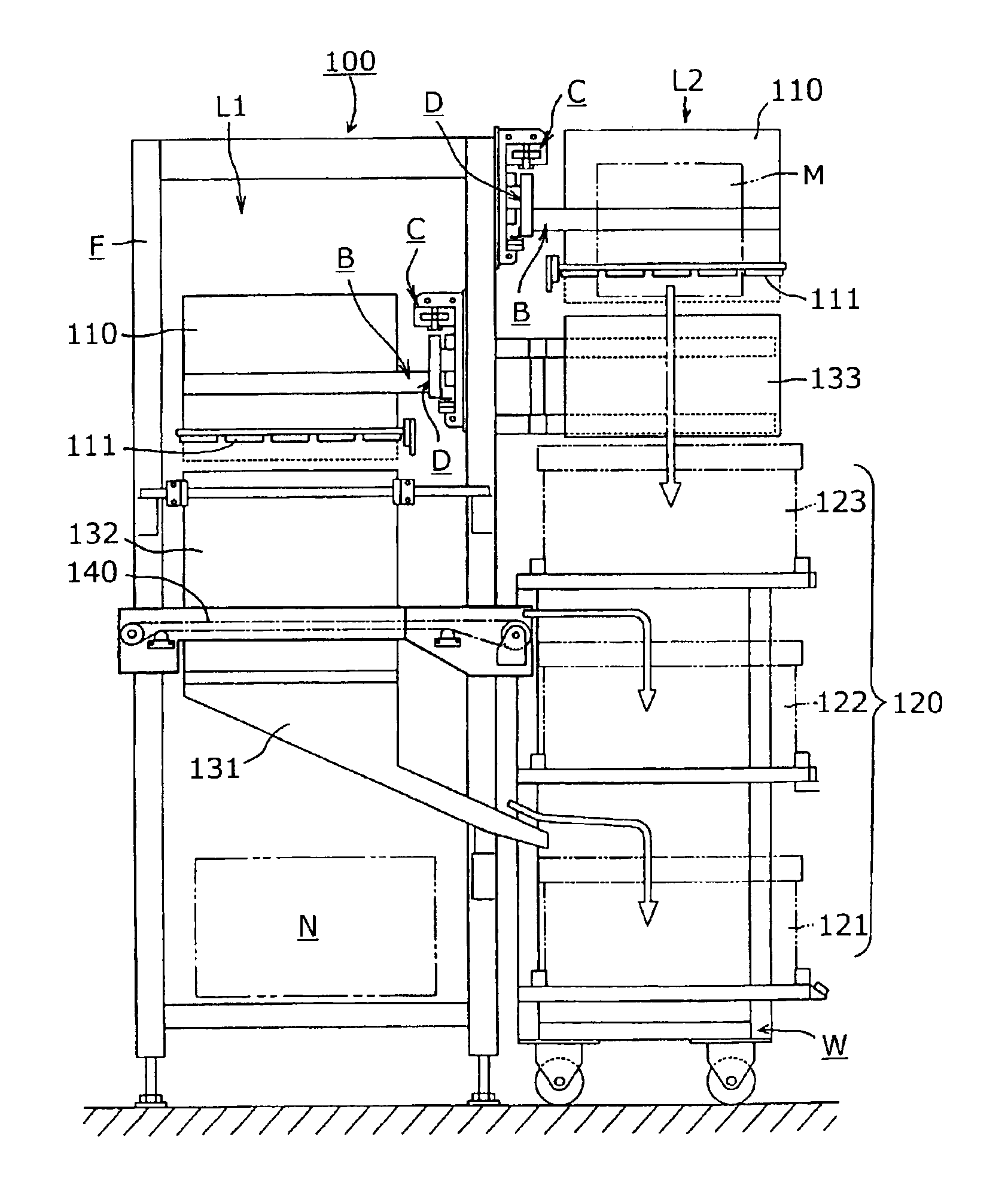
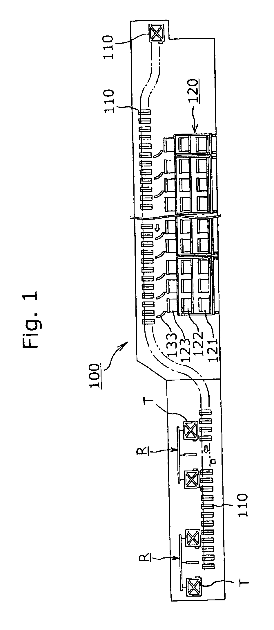
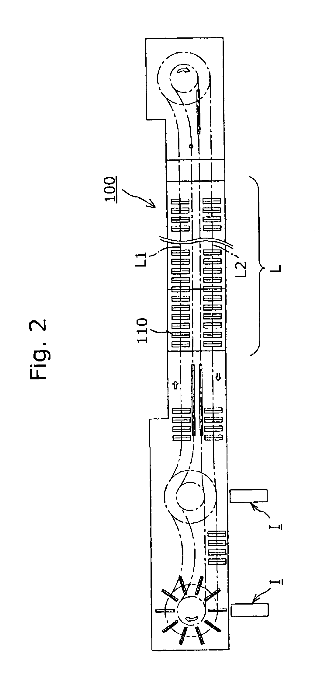
[0021]First, a mail sorter 100 according to the present invention shown in FIGS. 1 and 2 recovers the respective mail M (see FIG. 3) conveyed by a number of conveyor baskets, which move on a mail sorting line L in circulation in a forward run L1 and a return run L2 past a series of sorting receivers (not shown). Each receiver directs mail M into one of a plurality of layered mail recovery box groups 120. The reference characters I in FIG. 2 denote mail charging devices including a sorting receiver data reader for charging non-sorted mail M to the mail sorter 100 of the present invention, the reference characters R in FIG. 1 denote a mail sorting and distributing transfer system for receiving non-sorted mail M from the mail charging device I by use of transfer baskets and transferring the mail to the mail sorter 100 of the example according to the present invention, and the arrow in FIG. 2 denotes a direction of movement of the conveyor basket 110, which moves on the mail sorting lin...


PUM


Abstract

A mail sorter, which can reliably sort mail while avoiding the breakage and the recovery mistake of mail released from conveyor baskets, which move on the mail sorting line in circulation. The mail sorter has a conveyor line with a conveying forward run and a conveying return run closely arranged back to back with each, and layered mail recovery box groups are disposed along a lower region of the conveying return run in parallel to each other. The mail recovery box groups comprise lowest stage boxes for recovering mail M released from conveyor baskets on the conveying forward run through a transverse deflection chute, middle stage boxes for recovering mail M released from the conveyor baskets on the conveying forward run through a discharge chute, and uppermost stage boxes for recovering mail M released from the conveying baskets on the conveying return run through a buffer chute.

Description

FIELD OF THE INVENTION[0001]The present invention relates to a mail sorter, which sorts mail conveyed by a plurality of conveyor baskets, which are circulated along a mail sorting line, past every receiver which sorts the mail for a group of mail recovery boxes.BACKGROUND OF THE INVENTION[0002]As disclosed in, for example Japanese examined patent publication No. Sho. 63-8824, in a conventional mail sorter, mail recovery boxes are arranged in a series along the lower region of a mail sorting line in which a number of conveyor baskets circulate. Each recovery box is associated with a sorting operator or a sorting receiver which selects the recovery box to receive the mail from the conveyor basket. The conveyor baskets circulate past every sorting receiver in the series. The respective mail pieces are released from the conveyor baskets and are recovered in the mail recovery boxes selected by the receiver. It is noted that the term “mail” in the present invention means a sheet-shaped pi...

Claims


Application Information

Patent Timeline
IPC IPC(8): B07C3/02B07C3/08
CPCB07C3/082Y10S209/90
Inventor SHIIBASHI, RYOSUKEKANBE, TOSHIOSHIMOMURA, MASAKAZUYOSHIKAWA, SHIGERU
Owner TSUBAKIMOTO CHAIN CO
Why Eureka
Try Eureka