Transfer and sorting conveyor

A conveyor belt and sorting technology, applied in the field of conveyor belts, can solve problems such as difficult inspection and adjustment, inability to reduce the installation interval of sliders, timing deviation between sliders of switching mechanism and sorting signals, etc.

Inactive Publication Date: 2004-06-30
株式会社果実非破壊品质研究所 +1
View PDF1 Cites 0 Cited by
  • Summary
  • Abstract
  • Description
  • Claims
  • Application Information

AI Technical Summary

Problems solved by technology

That is to say, due to the restriction of the required length of the switching rail, there is a problem that the installation interval of the slider cannot be reduced.
[0006] Moreover, since the switching mechanism is installed in the lower part of the conveying surface in the frame, there is a disadvantage that when the chain is elongated through long-term use, the timing of both the slider and the sorting signal relative to the switching mechanism will occur. It is not easy to check and adjust for this when the

Method used


Image

  • Transfer and sorting conveyor
  • Transfer and sorting conveyor
  • Transfer and sorting conveyor

Examples


Embodiment

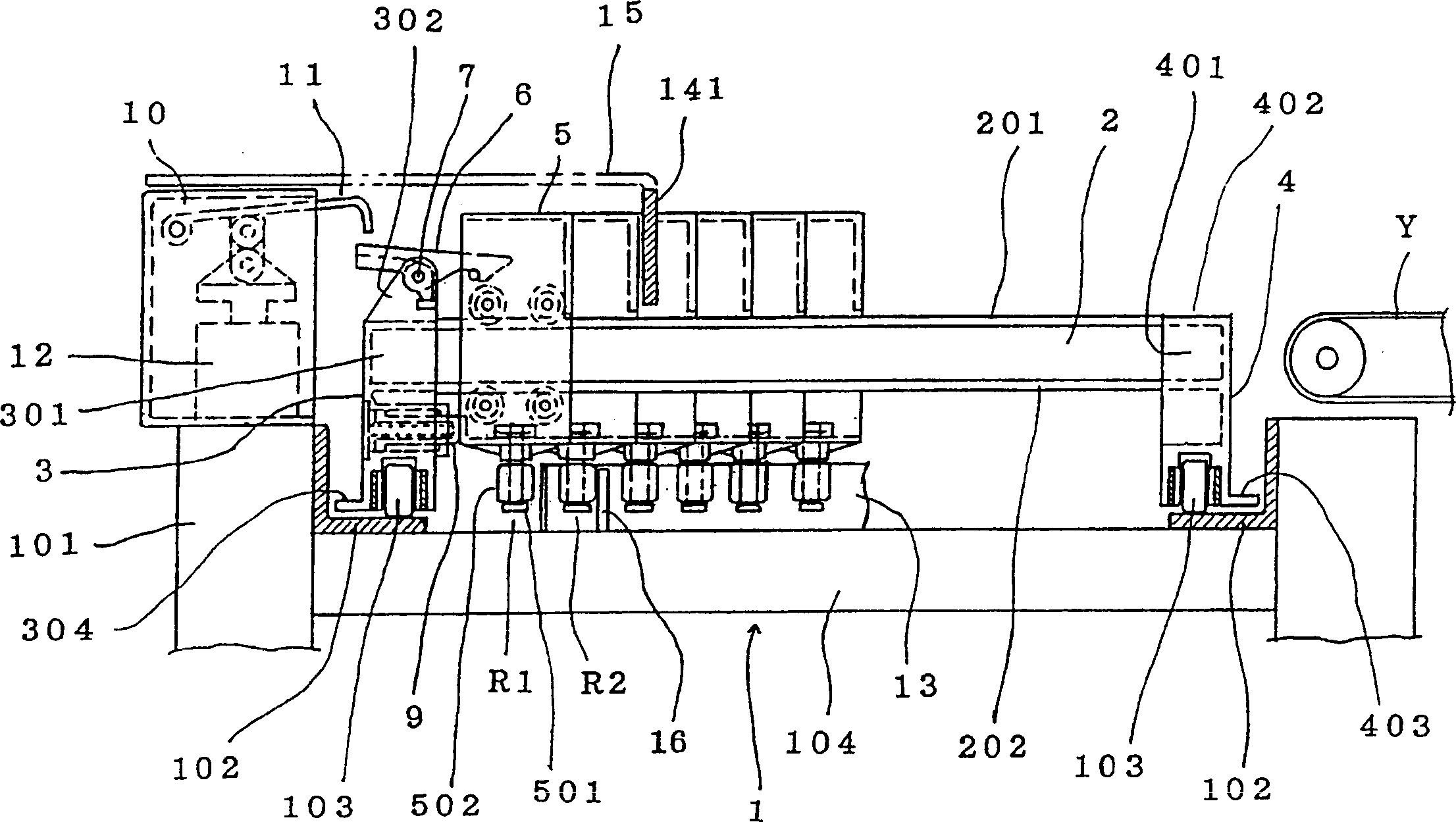
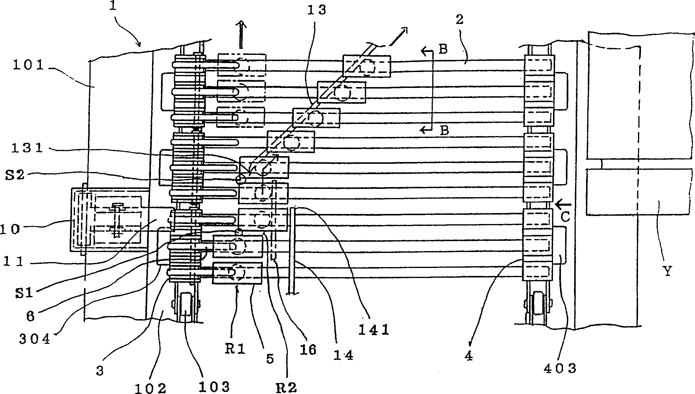
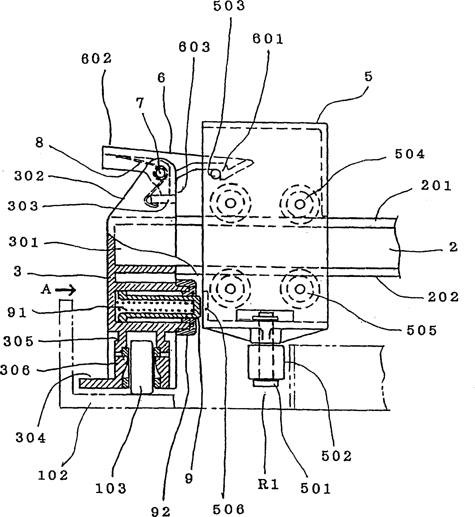
[0039] Below, the embodiments will be described in conjunction with the accompanying drawings. figure 1 is a sectional view of the main part of the sorting conveyor belt, figure 2 is the top view of its main parts, and the detailed structure is shown in Figure 3 ~ Figure 8 .

[0040] In the figure, as a conveyor belt 1, a closed conveyor belt chain 103 is arranged on a chain rail 102 arranged on the inner side of both sides of a frame 101, and the conveying surface forming members 2 are arranged in parallel between the conveyor belt chains 103, and the two ends pass through one side. The installation part 3 on the one side and the installation part 4 on the other side are respectively installed on the chains 103 on both sides.

[0041] Sliders 5 combined so as to be movable (hereinafter also referred to as lateral movement) in the longitudinal direction (hereinafter also referred to as the width direction of the conveyor belt) are respectively attached to each conveying su...


PUM


Abstract

A transfer and sorting conveyor capable of preventing a trouble with a pin of a slide block (5) of a high-speed traveling sorting conveyor (1) from occurring at a sorting point (S2), wherein a pusher means is installed on either of a mounting member (3) and the slide block on one side of a transfer surface forming member (2), the slide block is locked to one side in the state of being energized in the sorting direction, and the locking of the slide block is unlocked by an operation device (10) on the upstream side of the sorting point so as to laterally move the slide block from a straight traveling path (R1) to a sorting path (R2), and the laterally moved slide block is picked up by a sorting guide rail (13) extending from the sorting point in the sorting direction, and led in the sorting direction so as to push out small articles for sorting.

Description

technical field [0001] The present invention relates to a conveyor belt for sorting a series of articles transported from the previous process to a plurality of predetermined positions according to the purpose during the transport. Background technique [0002] In the past, as a mechanism for sorting the articles on the conveying surface laterally, for example, the scheme disclosed in the Japanese Patent Publication No. 8-615 is adopted, that is, a device is provided to push the articles laterally (sideways) to form the conveying surface. The slider on the slat or tubular roller, the slider is provided with a guide pin protruding downward from the slider or a guide roller installed to be freely rotatable, and the guide pin or guide roller is guided by the guide pin or guide roller. The trough is guided in sliding contact with the sorting guide rail branching from the straight guide trough, so that the slider slides laterally along the slats or tubular rollers, thereby either...

Claims


Application Information

Patent Timeline
Patent Type & Authority Patents(China)
IPC IPC(8): B65G47/84
CPCB65G2207/36B65G47/844B65G47/68
Inventor 前田弘原口和男
Owner 株式会社果実非破壊品质研究所
Why Eureka
Try Eureka