Electric valve

A technology of electric valves and needle valves, which is applied in the direction of valve lifts, valve details, valve devices, etc., can solve the problems of high cost, hindering the work of the valve body, and the inability to use the motor drive torque, etc., to achieve the effect of reducing costs

Active Publication Date: 2014-08-06
SAGINOMIYA SEISAKUSHO INC
View PDF8 Cites 0 Cited by
  • Summary
  • Abstract
  • Description
  • Claims
  • Application Information

AI Technical Summary

Problems solved by technology

[0009] However, the rotary force of the stepping motor (rotor magnet) is transmitted by the feed screw to move the valve body up and down to control the fluid. In the electric valve with such a structure, if the sludge and metal contained in the fluid If foreign matter such as powder enters the feed screw part, the feed screw part that slides while receiving a high load will become a cause of deterioration of sliding performance due to biting, damage, etc.
[0010] In this way, in the electric valve that uses the rotation of the motor to adjust the flow rate of the valve, in the worst case, it may not be able to operate using the driving torque of the motor.
[0011] However, in the electric valve of Patent Document 1, it is a structure for preventing the intrusion of mud into the gap of the needle insertion hole, and no consideration is given to the intrusion of foreign matter such as mud and metal powder into the threaded part.
[0012] Therefore, in the electric valve disclosed in Patent Document 1, foreign matter such as sludge and metal powder stays in the internal space of the rotor chamber, and these foreign matters enter the feed screw portion, causing the sliding performance to deteriorate due to bite, damage, etc. Furthermore, there is a problem that the operation of the valve body is hindered.
[0013] In addition, in the electric valve of Patent Document 2, a pressure equalizing hole is provided through the guide sleeve at a position away from the fixed threaded portion toward the valve chamber side, but no consideration is given to the intrusion of foreign matter such as sludge and metal powder into the threaded portion.
[0014] Therefore, also in the electric valve of Patent Document 2, foreign substances such as sludge and metal powder remain in the internal space of the rotor chamber, and these foreign substances enter the feed screw part, causing the sliding performance to deteriorate due to bite, damage, etc. , which in turn causes the problem of hindering the work of the valve body
[0015] In addition, in the electric valve of Patent Document 3, it is necessary to install expensive filters such as foamed metal and wire mesh, and the cost becomes high.

Method used


Image

  • Electric valve
  • Electric valve
  • Electric valve

Examples


Embodiment 1

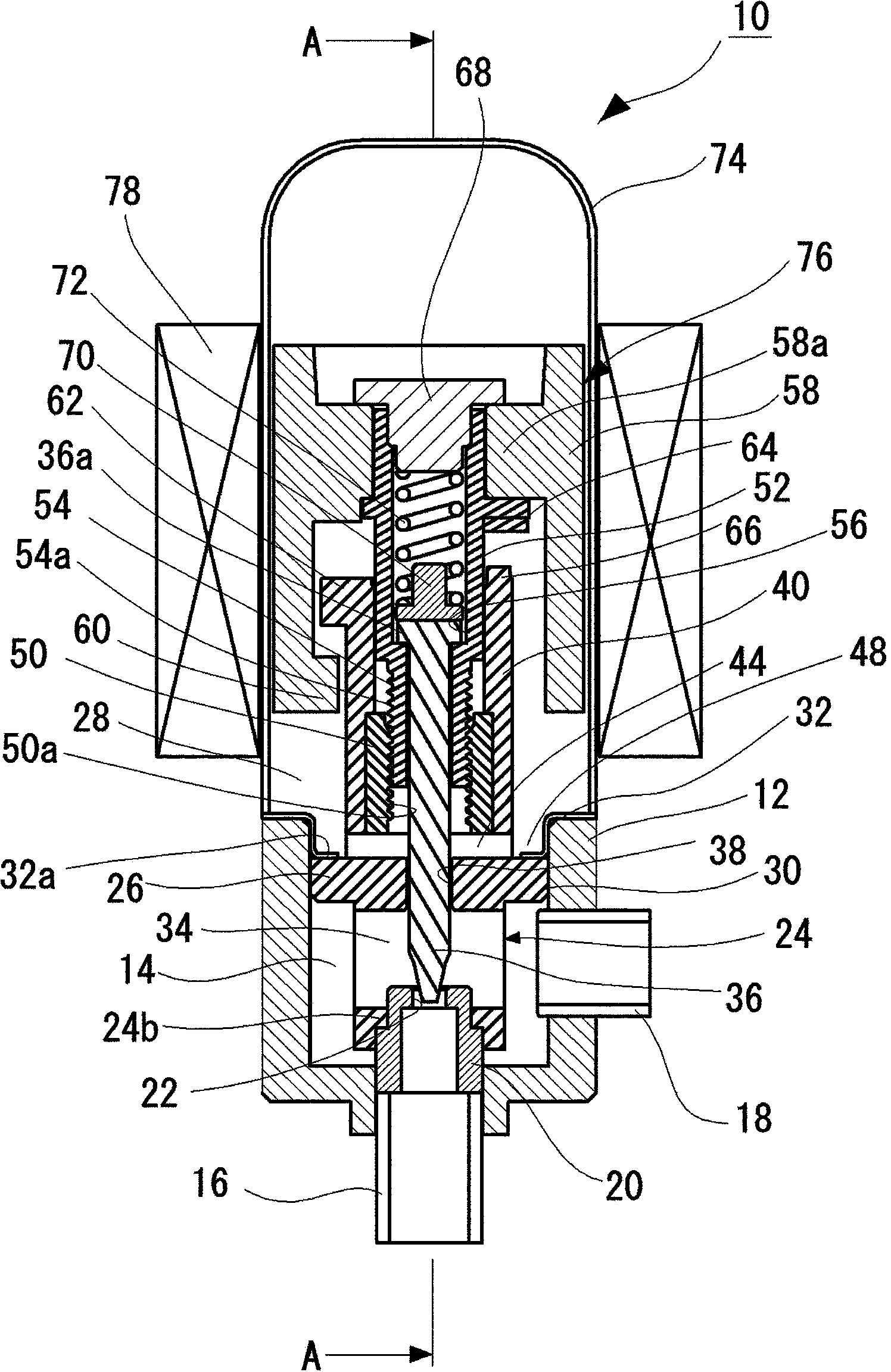
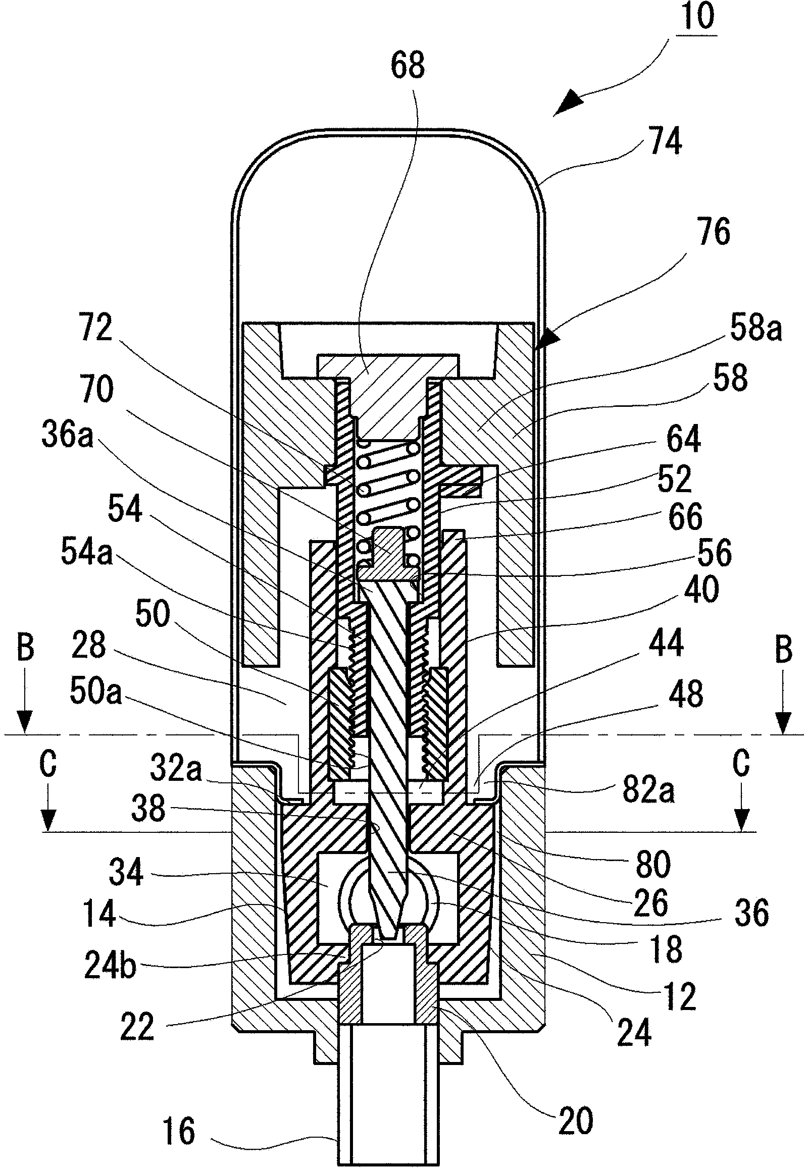
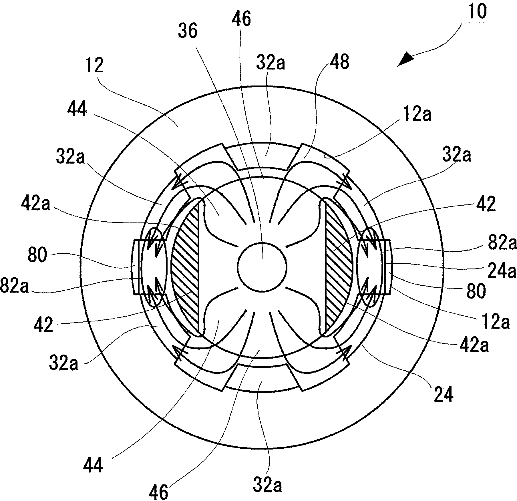
[0054] figure 1 It is a longitudinal sectional view of the valve opening state of the electric valve of the present invention, figure 2 yes figure 1 A longitudinal sectional view of line A-A, image 3 yes figure 2 A sectional view of the B-B line, Figure 4 yes figure 2 A cross-sectional view of line C-C, Figure 5 is closed valve state, and figure 1 The same longitudinal section view.

[0055] exist Figure 1 to Figure 5 In , the whole of symbol 10 represents the electric valve of the present invention.

[0056] Such as Figure 1 ~ Figure 2 As shown, the electric valve 10 of the present invention has a valve body 12 in which a valve chamber 14 is formed. Furthermore, a first pipe member 16 serving as an inlet joint and a second pipe member 18 serving as an outlet joint are attached so as to communicate with the valve chamber 14 .

[0057] In addition, a valve seat 20 is fixed to the valve main body 12 on the upper portion of the first piping member 16 , and a va...

Embodiment 2

[0092] Image 6 is another embodiment of the electric valve of the present invention, and image 3 The same cutaway view.

[0093] The configuration of the electric valve 10 of this embodiment is basically the same as the configuration shown in Embodiment 1, and the same components are given the same reference numerals, and detailed description thereof will be omitted.

[0094] In the electric valve 10 of this embodiment, as Image 6 As shown, four horizontal flow expansion passages 44 are formed on the guide portion 40 of the guide sleeve 24 .

[0095] On the other hand, four opposing communication outlets 46 are formed, and four deposition portions 82 of the outer annular flow path 48 where the fluids flowing in the outer annular flow path 48 merge with each other and the flow velocity is reduced are formed. Four vertical flow paths 80 are formed on the portion 82 .

[0096] Also in the motorized valve 10 of this embodiment, the same effect as that of the motorized valve...


PUM


Abstract

The present invention provides an electric valve. The foreign matters such as mud and metal powder contained in fluid do not invade into a feeding lead screw part. Sliding performance deterioration of a screw thread part because of nip, wound, etc. is prevented. Furthermore the valve can operate smoothly and reliably. Furthermore, no complicated structure is caused and the cost can be reduced. The electric valve is provided with the following components: a horizontal flow expanding path which has a cross section area that is larger than that of a needle valve so that the fluid that inflows from a valve chamber through a clearance between an insertion hole of a needle valve of a guiding sleeve and the needle valve flows from the center of the needle valve to outside in the horizontal direction; an outer annular flow path which is formed between the guiding sleeve and the inner wall of the valve body so that the fluid which passes through the horizontal flow expanding path annularly flows along the inner wall of the valve body in the horizontal direction; and a longitudinal flow path which is formed between the outer wall of the guiding sleeve and the inner wall of the valve body and is communicated with the valve chamber so that the fluid which flows in the outer annular flow path flows back into the valve chamber.

Description

technical field [0001] The present invention relates to electric valves such as flow control valves used in, for example, refrigerant circulation circuits of air conditioners such as air conditioners. Background technique [0002] Conventionally, in such an electric valve having a rotor magnet made of a permanent magnet, foreign substances such as sludge and metal powder flowing in the refrigerant flow path enter the drive unit together with the refrigerant, thereby hindering the operation of the electric valve. [0003] Therefore, conventionally, for example, Patent Document 1 (Japanese Unexamined Patent Publication No. 2000-320712 ) discloses a structure in which, in order to prevent foreign matters such as sludge and metal powder from intruding into the needle-shaped insertion hole and the needle-shaped gap, the valve main body A communication hole connecting the valve chamber and the rotor chamber is arranged on the top. [0004] In addition, Patent Document 2 (Japanese...

Claims


Application Information

Patent Timeline
Patent Type & Authority Patents(China)
IPC IPC(8): F16K1/32
CPCF16K1/32F16K27/029F16K31/0655F16K31/0675
Inventor 中野诚一日下直树宫寺佑孝
Owner SAGINOMIYA SEISAKUSHO INC
Why Eureka
Try Eureka