
Disc brake

A power transmission device, pressure technology, applied in the direction of automatic clutch, mechanical drive clutch, clutch, etc., can solve problems such as noise and vibration, and achieve the effect of reducing rattle

Active Publication Date: 2017-05-24
FCC KK
View PDF8 Cites 13 Cited by
  • Summary
  • Abstract
  • Description
  • Claims
  • Application Information

AI Technical Summary

Problems solved by technology

In this case, there is a problem in that the reaction torque limiter cam is constructed in order to assemble the clutch member and the pressure member with the cam faces of the press contact auxiliary cam facing each other and the cam faces of the reaction torque limiter cam facing each other. The gap between a pair of cam faces must be set fairly large, this gap produces rattle, noise, and vibration

Method used


Image

  • Disc brake
  • Disc brake
  • Disc brake

Examples


Embodiment Construction

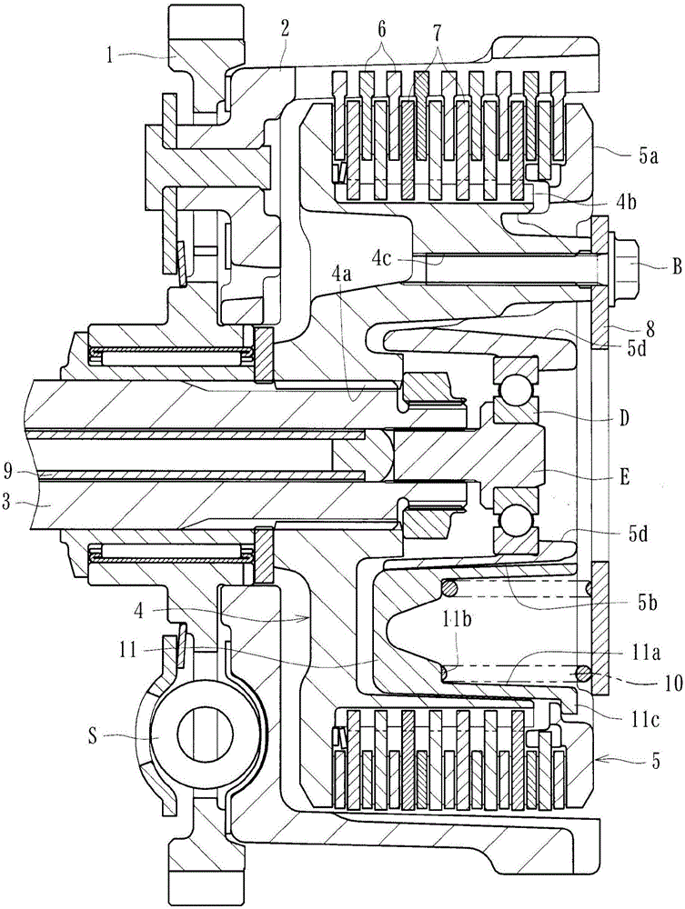
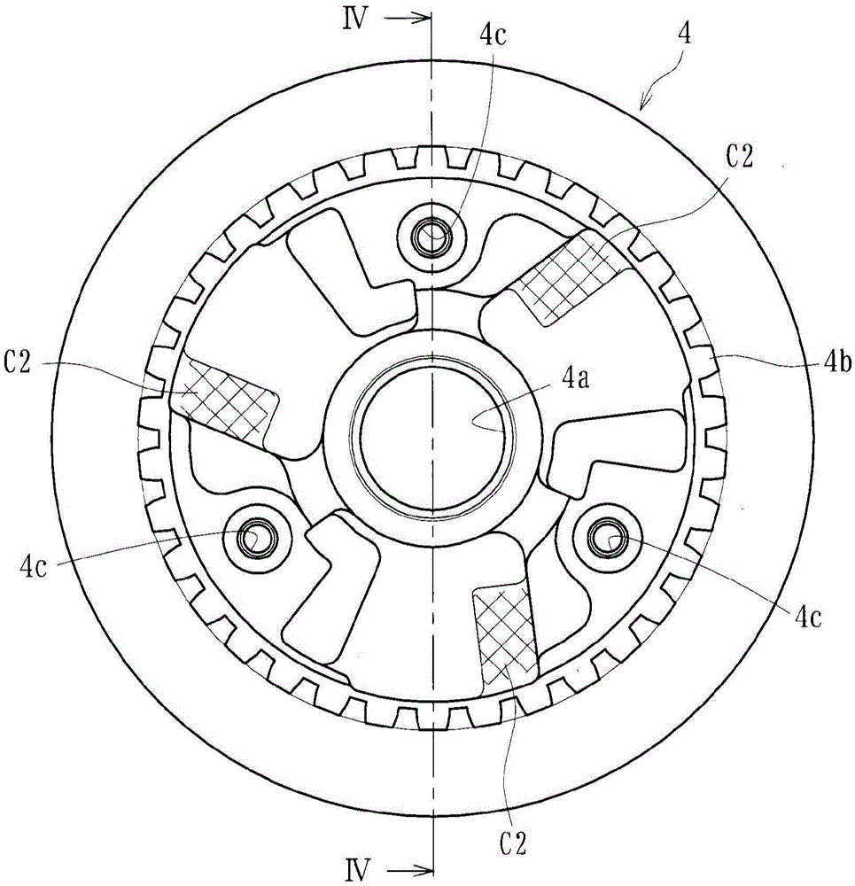
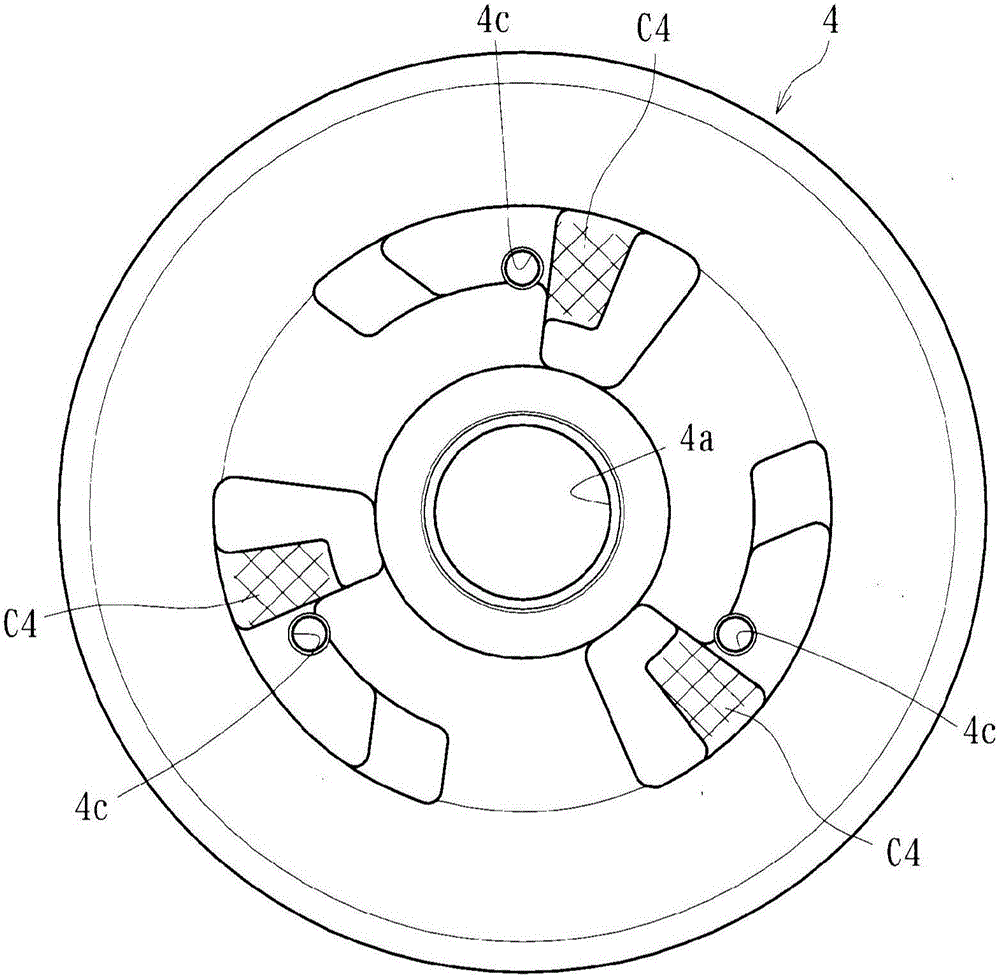
[0046] Hereinafter, embodiments of the present invention will be described in detail with reference to the accompanying drawings. The power transmission device according to this embodiment is mounted on a vehicle such as a motorcycle to arbitrarily transmit the driving force of the engine to the transmission or drive wheels or to interrupt the transmission. Such as figure 1 As shown in , the power transmission device mainly includes: a clutch housing 2 on which a gear 1 as an input member is mounted; a clutch member 4 connected to a shaft 3 as an output member; The pressure member 5 at the right end in the figure; the driving clutch plate 6 connected to the clutch housing 2 and the driven clutch plate 7 connected to the clutch member 4; the fixed member 8; the push rod 9; the clutch spring 10 as a biasing mechanism; and at least one receiving member 11 . In the drawings, reference sign S denotes a damper, and reference sign D denotes a ball bearing.

[0047] The gear 1 is ...


PUM


Abstract

Provided is a disc brake for which the ease when assembling a friction pad on a mounting member can be improved. The ear sections (7B, 7C) of a friction pad (6) are inserted in a pad guide (3) of a mounting member (2). A side-pressing spring (26) that presses in the rotation direction of a disc (1) is provided on the friction pad (6). Between the mounting member (2) and the friction pad (6), a pad spring (11) is disposed. The pad spring (11) is mounted so as to be able to abut against the pad guide (3) of the mounting member (2) and comprises guide plate sections (15) for guiding the friction pad (6) in the axial direction of the disc (1) and guiding projections (15C) that extend from outer sections (15A) of the guide plate sections (15) outward in the disc axis direction. The guiding projections (15C) are inclined in the disc rotation direction.

Description

technical field [0001] The present invention relates to a power transmission device capable of arbitrarily transmitting a rotational force of an input member to an output member or interrupting the transmission. Background technique [0002] In general, a power transmission device for a motorcycle is intended to transmit or interrupt the driving force of an engine to a transmission and drive wheels. Such a power transmission device generally includes an input member connected to the engine side, an output member connected to the transmission and drive wheel sides, and a clutch member connected to the output member. The power is transmitted by pressing a plurality of driving clutch plates with the driven clutch plates, and the transmission of the power is interrupted by releasing the pressing contact force. [0003] More specifically, as disclosed in, for example, Patent Document 1, a conventional power transmission device includes a clutch housing that rotates with the rota...

Claims


Application Information

Patent Timeline
Patent Type & Authority Applications(China)
IPC IPC(8): F16D43/21F16D13/52
CPCF16D7/027F16D2013/565F16D13/56F16D13/52F16D43/21F16D13/02F16D23/12F16D2023/123
Inventor 片冈真曾恒香青野薰
Owner FCC KK
Learn More