Differential data transmitter

a data transmitter and data technology, applied in the field of differential data transmitters, can solve problems such as difficulty in realizing an optimal pre-emphasis period

Inactive Publication Date: 2005-05-24
KK TOSHIBA
View PDF2 Cites 45 Cited by
  • Summary
  • Abstract
  • Description
  • Claims
  • Application Information

AI Technical Summary

Benefits of technology

[0044]FIGS. 11A and 11B are schematic views respectively showi

Problems solved by technology

In this respect, since the conventional differential data transmitter has an output section in which th

Method used


Image

  • Differential data transmitter
  • Differential data transmitter
  • Differential data transmitter

Examples


Embodiment Construction

[0045]Embodiments of the present invention will be described hereinafter with reference to the accompanying drawings. In the following description, the constituent elements having substantially the same function and arrangement are denoted by the same reference numerals, and a repetitive description will be made only when necessary.

[0046]

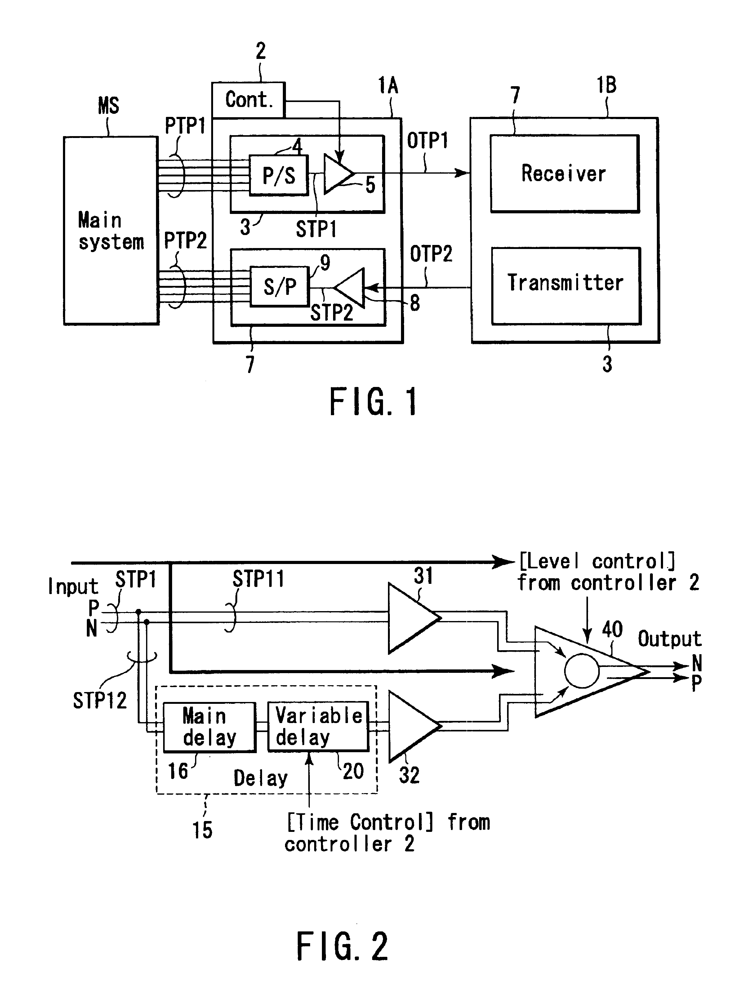
[0047]FIG. 1 is a block diagram schematically showing a high-speed serial data transmission system including a differential data transmitter-receiver apparatus according to a first embodiment of the present invention. This data transmission system includes a differential data transmitter-receiver apparatus 1A according to the first embodiment, and a differential data transmitter-receiver apparatus 1B connected to the transmitter-receiver apparatus 1A through external transmission paths OTP1 and OTP2, and disposed as a communication opposite-party thereof. A detailed explanation will be given only of the differential data transmitter-receiver apparat...


PUM


Abstract

A differential data transmitter includes a first pre-driver configured to receive a differential data signal, a delay circuit configured to receive the differential data signal in parallel with the first pre-driver, and output the differential data signal with a delay time, and a second pre-driver configured to receive an output signal from the delay circuit. The delay circuit is capable of changing the delay time in accordance with a control signal. An output driver is configured to receive first and second output signals from the first and second pre-drivers, and output a pre-emphasis waveform signal that corresponds to a subtraction signal between the first and second output signals.

Description

CROSS-REFERENCE TO RELATED APPLICATIONS[0001]This application is based upon and claims the benefit of priority from the prior Japanese Patent Application No. 2002-250274, filed Aug. 29, 2002, the entire contents of which are incorporated herein by reference.BACKGROUND OF THE INVENTION[0002]1. Field of the Invention[0003]The present invention relates to a differential data transmitter, and more particularly to an improvement of a pre-emphasis function in the output section of the transmitter. For example, the differential data transmitter is used in a high-speed serial data transmission system, such as a router that handles data of about 3.2 Gbps, or a mount board that performs data transmission between LSI chips.[0004]2. Description of the Related Art[0005]In a high-speed serial data transmission system, it is preferable to ensure a sufficient eye pattern (the eye pattern is an opening observed at the center when overlapping signal waveforms) in a differential data signal received b...

Claims


Application Information

Patent Timeline
IPC IPC(8): H04L25/02H03K5/125H03K19/0175
CPCH04L25/0278H04L25/0288H04L25/0292H04L25/0282
Inventor SATO, KIYOHITO
Owner KK TOSHIBA
Why Eureka
Try Eureka