Snowshoe with two degrees of rotational freedom

a technology of rotational freedom and snowshoes, applied in the field of snowshoes, to achieve the effect of simple and straightforward snowshoe design

Inactive Publication Date: 2005-05-31
K 2 CORP
View PDF15 Cites 33 Cited by
  • Summary
  • Abstract
  • Description
  • Claims
  • Application Information

AI Technical Summary

Benefits of technology

[0005]The invention described herein achieves a second degree of rotational freedom, for movement within the frontal plane or about the roll axis of the snowshoe, in an efficient manner which still provides the benefit of a relatively simple and straightforward snowshoe design. This second degree of freedom is combined with the typically permitted rotation about the traverse or pitch axis, also preferably spring-biased toward a pre-selected “zero” position. At the same time, the configuration of the invention substantially prevents any rotation of the snowshoe in the yaw direction, about a vertical axis, which rotation would tend to be unstable and awkward and would cause discomfort and instability.
[0007]Another configuration allowing two degrees of freedom uses strap suspension, somewhat similar to the front harness binding shown in the above Atlas Snow-Shoe Company patents. In this case, however, the support straps support a longitudinally extending rod or mounting device along a roll axis rather than supporting the footbed itself. The footbed is then secured to the rod or other pivot mounting so as to allow for the desired roll rotation. The rod can be a torsion rod, providing the needed bias. In this way, a simple support mechanism provides two degrees of spring-biased rotational freedom.
[0009]A variation of the above is achieved in a molded snowshoe, preferably of fiber-reinforced plastic. Integrally molded arms extend in a forward direction within the snowshoe body, cantilevered from back ends of the arms. The front ends of the arms allow spring-biased roll freedom when a footbed is secured via these forward arm ends.

Problems solved by technology

In this case, however, the support straps support a longitudinally extending rod or mounting device along a roll axis rather than supporting the footbed itself.

Method used


Image

  • Snowshoe with two degrees of rotational freedom
  • Snowshoe with two degrees of rotational freedom
  • Snowshoe with two degrees of rotational freedom

Examples


Embodiment Construction

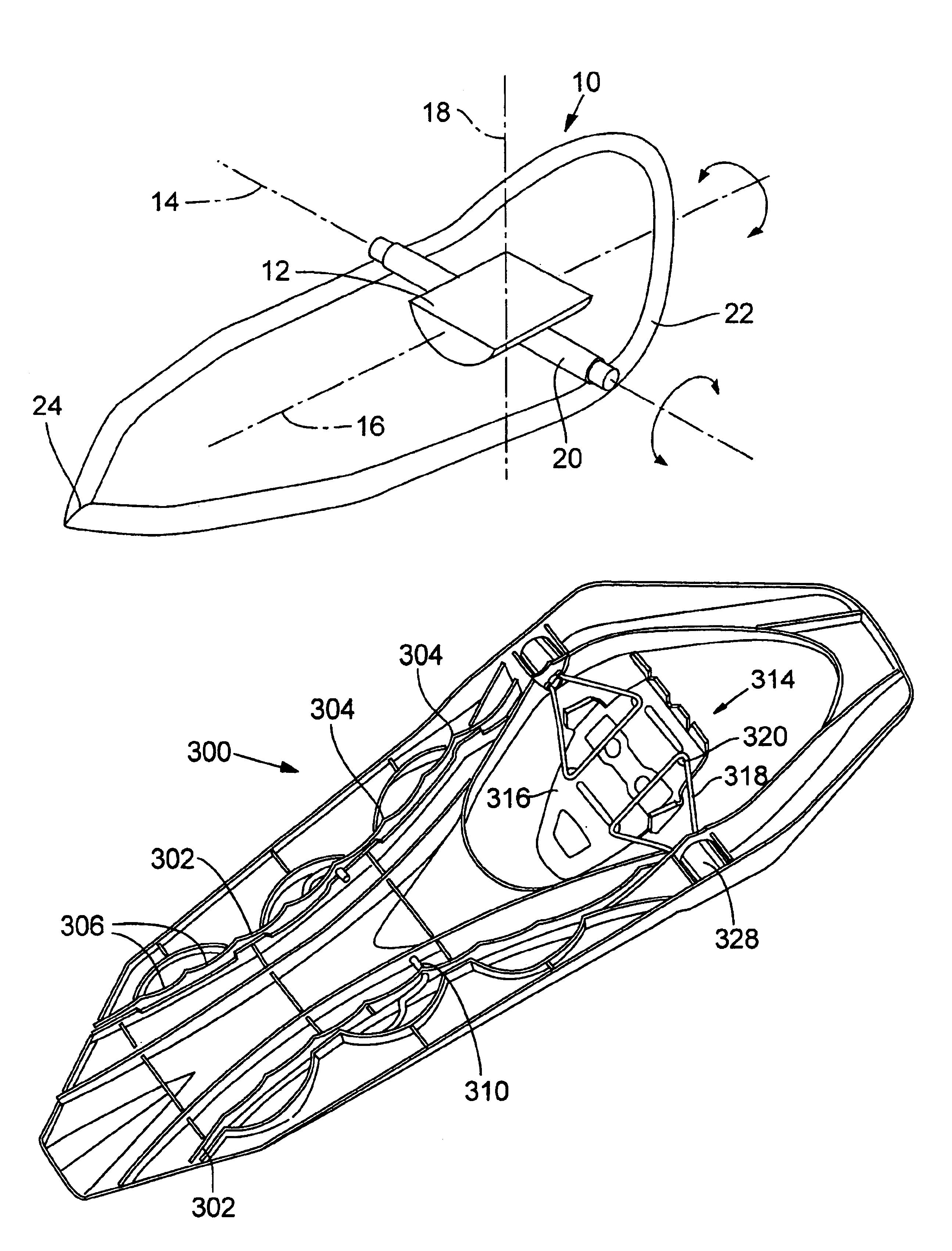
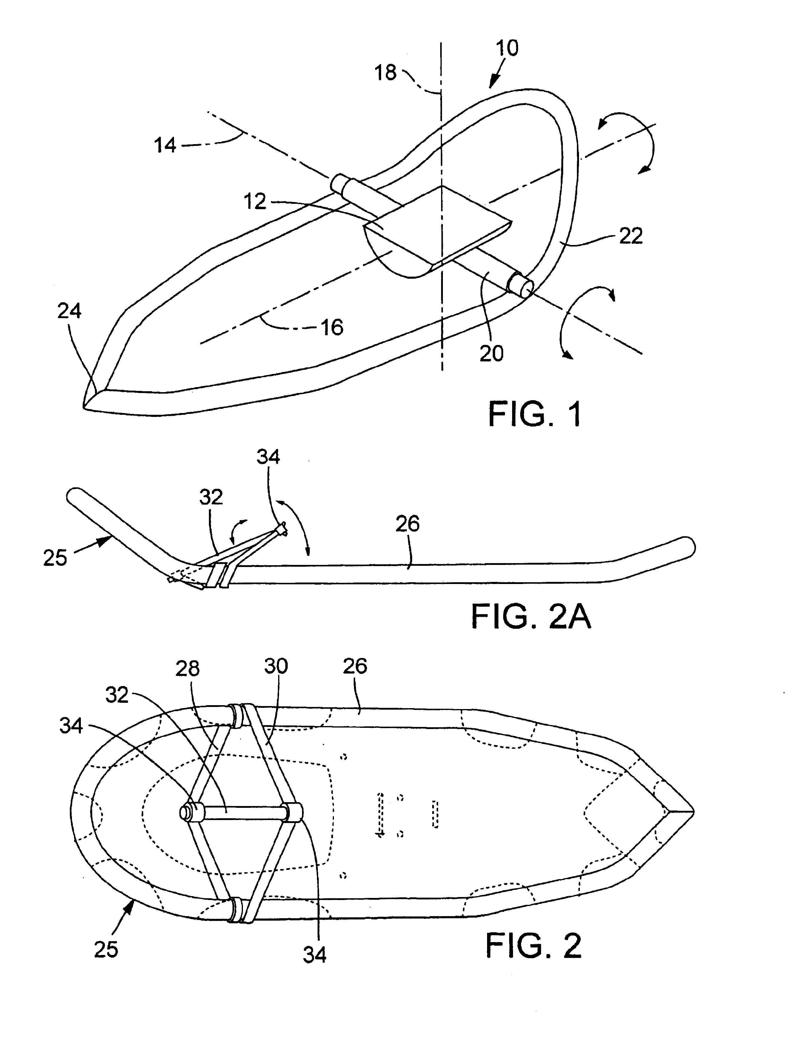
[0043]FIG. 1 indicates conceptually the framework and principles of the invention, showing potential rotational axes of a snowshoe relative to the user's boot, or to a footbed 12 to which the user's boot is secured. These axes of rotation, as mentioned above, are a transverse horizontal axis 14, or pitch axis, regarding potential rotation in the sagittal plane; the longitudinal horizontal axis 16 or roll axis, pertaining to rotation in the frontal plane; and the vertical axis or yaw axis 18, regarding rotation within a horizontal plane. This latter rotation is wholly undesirable and leads to instability in use of the snowshoe. Rotation about the yaw axis is to be avoided as nearly as possible.

[0044]A rotation about the pitch axis, within the sagittal plane, is desirable as discussed previously, and has been provided for in numerous previous snowshoes of Atlas Snow-Shoe Company and others. In the schematic perspective view of FIG. 1, this rotation is indicated as occurring via a bar ...


PUM


Abstract

A snowshoe has a pivoted mounting on its boot harness, for rotation about a pitch axis for a first degree of freedom in movement of the user's boot relative to the snowshoe; and provision for a second degree of freedom of motion along a roll axis, allowing the user's boot to tip from side to side, particularly for uneven or sidehill terrain. In both axes the boot preferably is spring-biased toward a neutral position. At the same time, freedom of movement is restricted and essentially prevented between the boot and snowshoe relative to a third axis, the yaw or vertical axis. Several different structural arrangements are disclosed in several types of snowshoes, for achieving the second degree of freedom.

Description

BACKGROUND OF THE INVENTION[0001]The invention relates to snowshoes, and more specifically is concerned with the freedom of movement afforded between the user's boot and a snowshoe. The invention provides for addition of some rotational freedom about a roll axis, i.e., within a frontal plane, to make more comfortable, safe and convenient the traversing of hillsides where the snowshoe cannot be planted flatly on terrain.[0002]A considerable number of snowshoes provide for freedom of movement of the user's foot and boot relative to the snowshoe on a pitch axis, that is, a traverse horizontal axis below the boot. This aids in walking over terrain where the user naturally tends to tip the foot, toe-downwardly, as the opposite foot is advanced and as the foot is lifted and moved forward, and avoids tripping the toe end of the snowshoe in the snow. Such pivoting has been achieved by supporting the boot footbed on support straps, as in Atlas Snow-Shoe Company's U.S. Pat. Nos. 5,440,827, 5,...

Claims


Application Information

Patent Timeline
Patent Type & Authority Patents(United States)
IPC IPC(8): A43C15/00A43B5/00A43B5/18A63C13/00
CPCA43B5/18A43C15/00A63C13/006A63C13/005A63C13/003
Inventor EMERSON, DANIEL T.SAMUELS, RUDY LUCASWARNER, CHARLES BENTLEY
Owner K 2 CORP
Why Eureka
Try Eureka