Electrostatic switched radiator for space based thermal control

Inactive Publication Date: 2005-05-31
SENSORTEX
View PDF23 Cites 6 Cited by
  • Summary
  • Abstract
  • Description
  • Claims
  • Application Information

AI Technical Summary

Benefits of technology

[0015]The ESR construction is simple and lightweight. It consists of a thin polymer film, with a weight of less than a few hundred grams/m2. The film can be anchored to the craft/spacecraft at the edges. The cover film consists of a high dielectric constant insulator with a good dielectric strength and is coated on its outer surface with an electrically conductive thin layer. The outer surface of the ESR is constructed to have a very high emissivity, ideally with low visible absorbance. This combination can be achieved with an appropriate paint or, for better performance, a multi-layer thin film designed for very low visible absorbance and high emissivity. The top surface or “skin” of the craft/spacecraft, to which the ESR will be “in contact” or “not in contact” should have a very low emissivity, i.e. sputtered gold.
[0016]Basic heat control is simple and highly effective. When the ESR is turned on, the emitting surface is in good thermal contact with an inner surface skin (such as the outer skin of a spacecraft). This results in good heat conduction between the craft surface (skin) and the ESR such that the emitting surface of the film is at the craft skin temperature. The emitting ESR surface radiates at the “skin” temperature (high emissivity state). When the ESR is turned off, the film moves away from the skin (is not in contact) and the heat flow is only radiation from the inner surface skin (low emissivity). Thus, once it reaches equilibrium, the film can only radiate the heat it absorbs which is limited to radiation from the inner surface skin. The inner surface skin is fabricated with a low emissivity and thus in the released state, the outer skin emissivity doesn't change, however it's temperature drops and the result is a drop in the radiated energy. This app

Problems solved by technology

When radiators are fixed, as in present art, options including heat pipes, heat pump systems, c

Method used


Image

  • Electrostatic switched radiator for space based thermal control
  • Electrostatic switched radiator for space based thermal control
  • Electrostatic switched radiator for space based thermal control

Examples


Example

[0028]Before explaining the disclosed embodiment of the present invention in detail, it is to be understood that the invention is not limited in its application to the details of the particular arrangement shown, since the invention is capable of other embodiments. Also, the terminology used herein is for the purpose of description and not of limitation.

DETAILED DESCRIPTION OF DRAWINGS

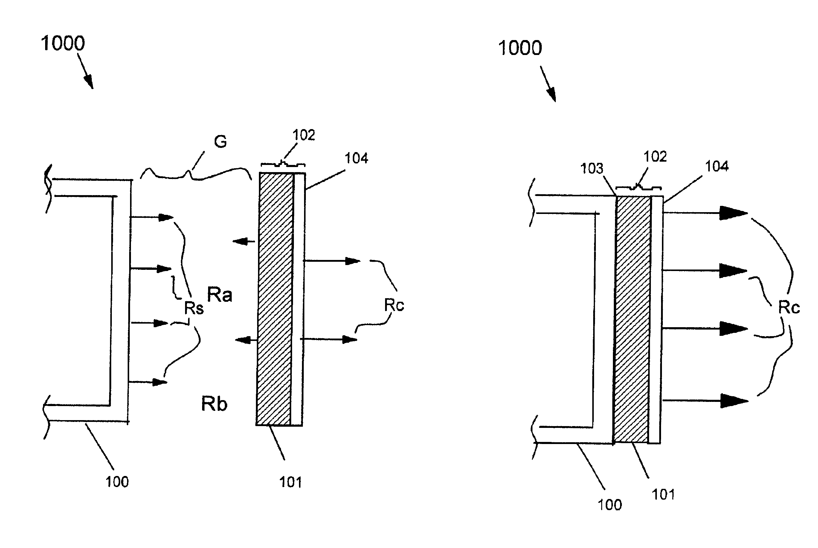
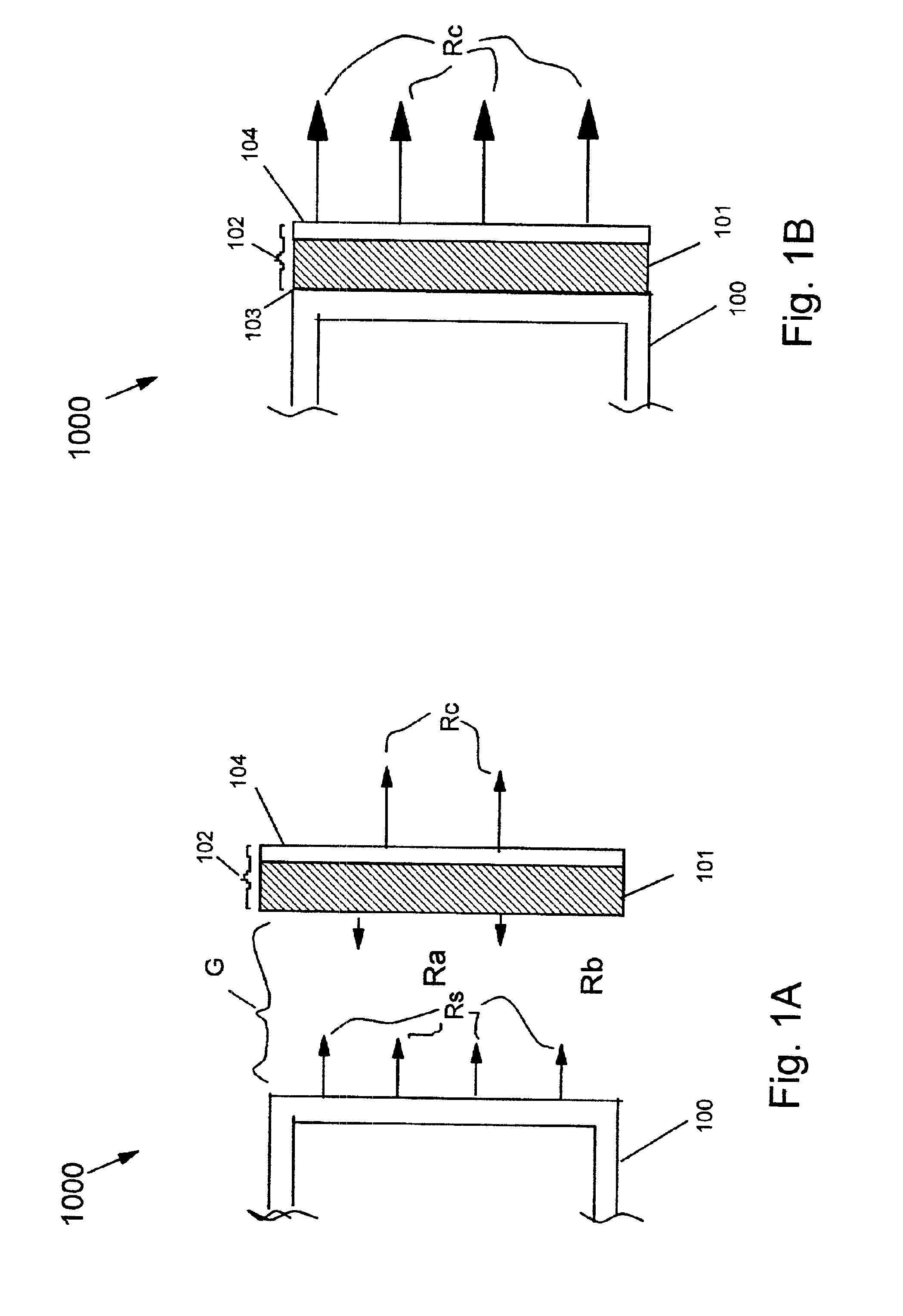
[0029]FIG. 1A is a depiction of the ESR 1000 in the “OFF” state. The outer skin 100 of a craft radiates heat via radiation Rs. Thermal gap G acts as an insulator. Energy is radiated Rs by the outer skin 100, which has a low surface emissivity. Heat is absorbed by the composite film 102 consisting of the dielectric 101 and the thin metallic surface coat 104. In this “OFF” position, the heat loss from the outer skin 100 is the energy lost from radiation emitted Rs minus the energy absorbed from the reflected radiated energy Ra of the composite film 102 (dielectric 101 and thin metallic surface coat 104) ...


PUM

PropertyMeasurementUnit
Temperatureaaaaaaaaaa
Flexibilityaaaaaaaaaa
Electric potential / voltageaaaaaaaaaa

Abstract

A thermal control device for controlling the temperature of a craft/spacecraft is an electrostatic switch causing a large change in apparent emissivity. A flexible covering has a high emissivity and makes close contact with the surface of the spacecraft when electrostatically attracted thereto, when the covering is out of contact, the spacecraft surface emissivity controls radiation. The device can operate with moderate levels of DC voltages. Application of voltage results in high emissivity while removal of voltage allows a separator to move the covering out of contact and thus results in low emissivity.

Description

FIELD OF THE INVENTION[0001]The present invention relates to an improved device for controlling the effective emissivity of a surface by use of electrostatic attraction, which controls the thermal conductivity.BACKGROUND OF THE INVENTION[0002]Control of solar absorption and / or thermal emissivity is important for temperature control involving systems where radiation is the major heat control mechanism. Control of black body radiation and solar absorption, using spectrally selective coating, will help control the temperature. But, when the heat load varies, active control of the thermal radiation is needed. Coolants have been used to conduct heat to an external radiator and can be controlled to block, or to be open, to piping. Louvers are another alternative that can be used to open or close. With a louver in one position, the exposed surface will have a high emissivity; alternately when the louvers is in the other position, the exposed surface will have a lower emissivity and will ra...

Claims


Application Information

Patent Timeline
IPC IPC(8): B64G1/46B64G1/50
CPCB64G1/503F28F2013/008
Inventor BITER, WILLIAM J.OH, SUNG J.HESS, STEPHEN M.
Owner SENSORTEX
Why Eureka
Try Eureka