Light emitting device and lighting fixture

Active Publication Date: 2015-06-04
NICHIA CORP
View PDF1 Cites 2 Cited by
  • Summary
  • Abstract
  • Description
  • Claims
  • Application Information

AI Technical Summary

Benefits of technology

[0019]The light emitting device pertaining to the present disclosure affords both good heat dissipation and good dielectric strength to be achieved, even when the device is used as a high-output light source in which a plurality of li

Problems solved by technology

And with a conventional light emitting device, if an attempt is made to ensure good dielectric strength, heat dissipation performance may end up suffering if an insulating sheet is sandwiched at the rear face of the light emitting device, for example.
Also, with a conventional light emitting device, the sheet surface area has to be large enough to achieve an adequate creepage distance to the end of the metal substrate, and this hampers efforts to make the device more compact, and makes it difficult to achieve both good heat dissipation and good dielectric strength.
Meanwhile, with a ceramic substrate package with high dielectric strength, the higher is the output, the lower is the thermal conductivity, and consequently heat can become trapped inside the light emitting device, which is a problem in that it reduces efficiency and shortens the service life.
Also, just as with a metal substrate package, raising the dielectric strength requires a larger creepage distance from the power supply terminal to the ceramic substrate end face, and this makes it harder to reduce the size.
With a conventional light emitting device, however, the thermal conductivity of the ceramic material used for the mounti

Method used


Image

  • Light emitting device and lighting fixture
  • Light emitting device and lighting fixture
  • Light emitting device and lighting fixture

Examples


Example

[0030]In the following embodiment, however, the light emitting device and the lighting fixture that embody the technological concept of the present disclosure are just examples, and unless otherwise specified, the dimensions, materials, shapes, relative layout, and so forth of the constituent parts discussed in the embodiment are not intended to limit the scope of the present disclosure, and are merely examples given for the sake of illustration. Further, constitutions described in examples and the embodiments can be employed in other examples and embodiments. The sizes and the arrangement relationships of the members in each of drawings are occasionally shown exaggerated for ease of explanation. Moreover, in the description below, the same designations or the same reference numerals may, in principle, denote the same or like members and duplicative descriptions will be appropriately omitted.

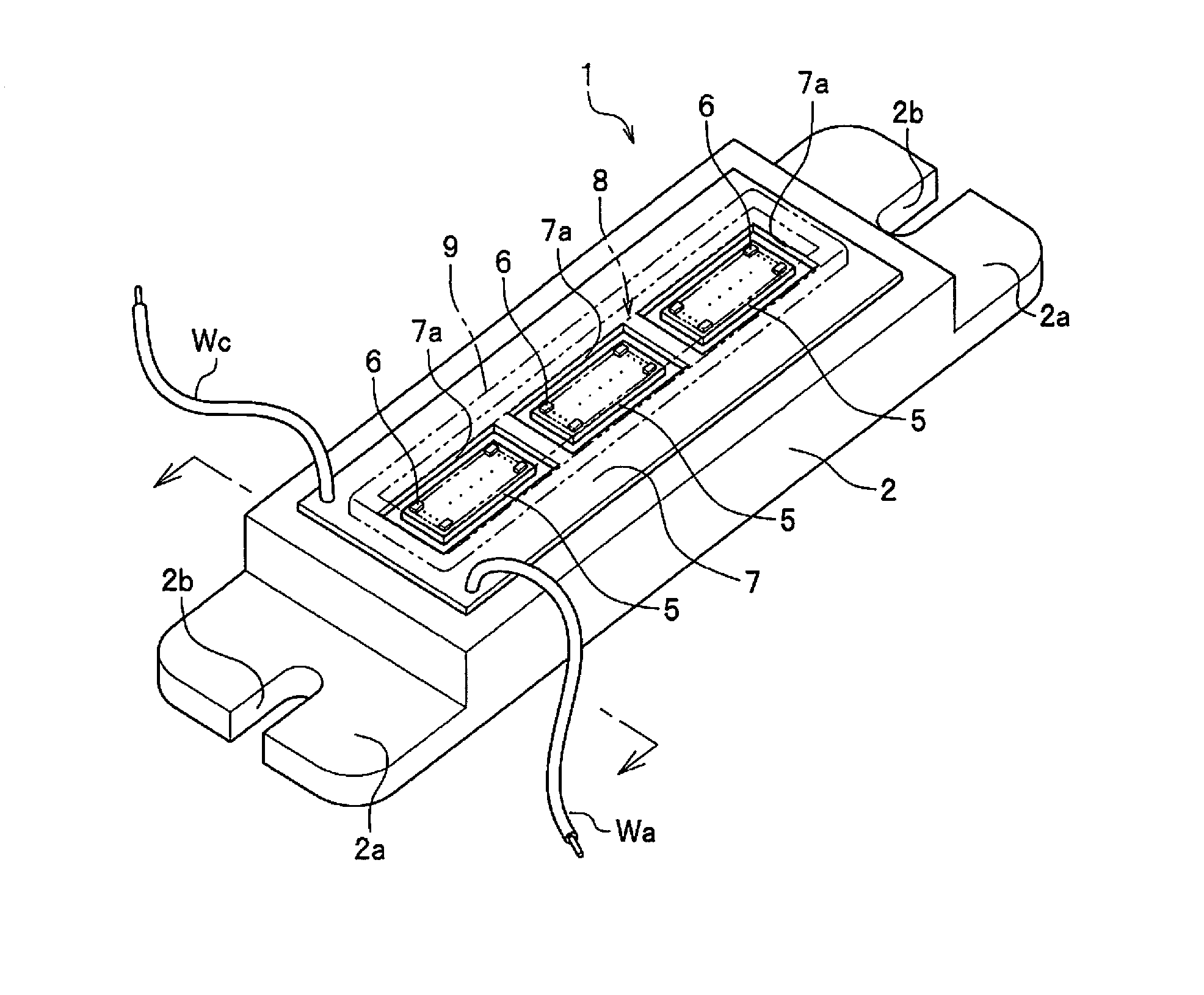
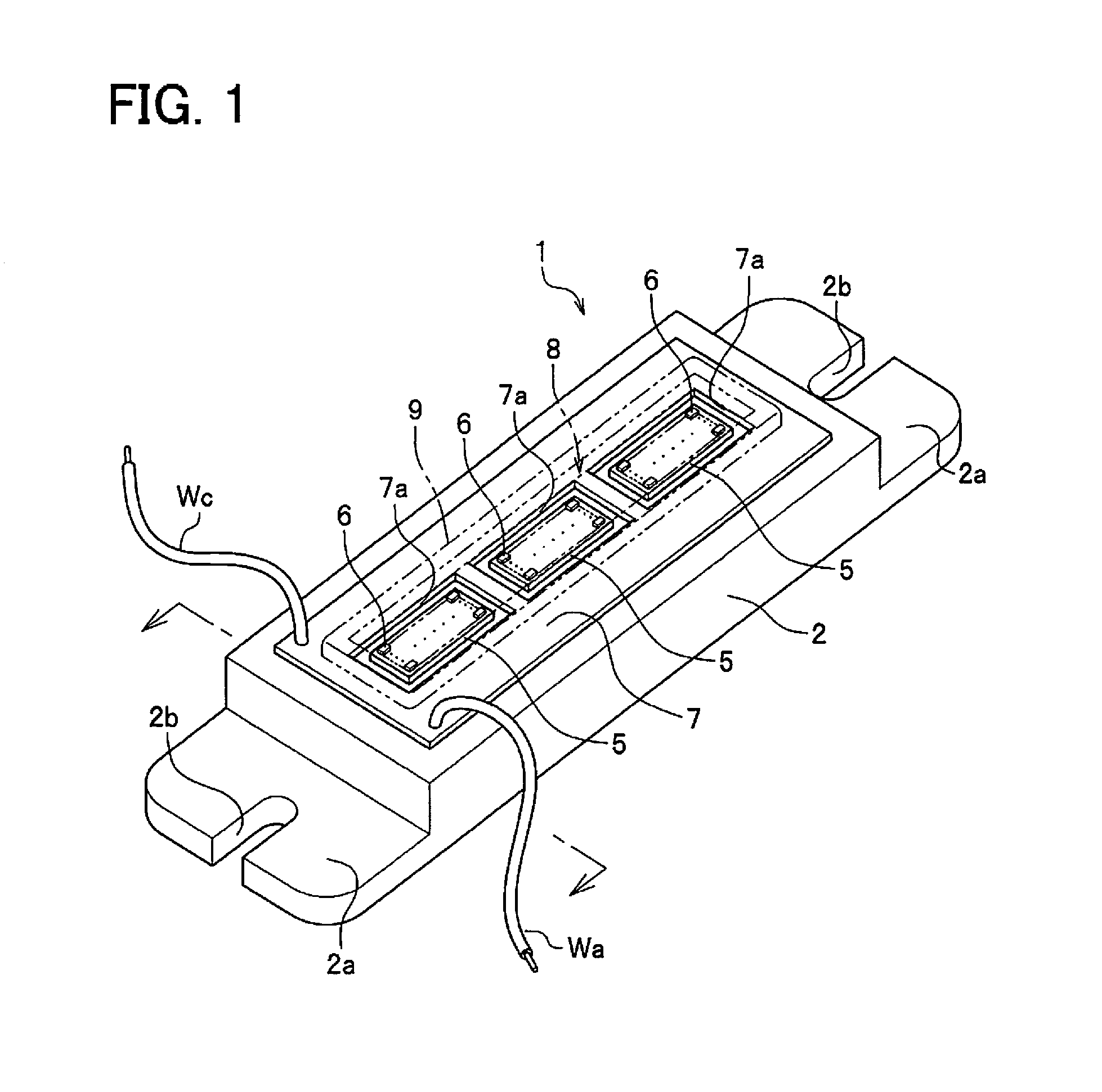
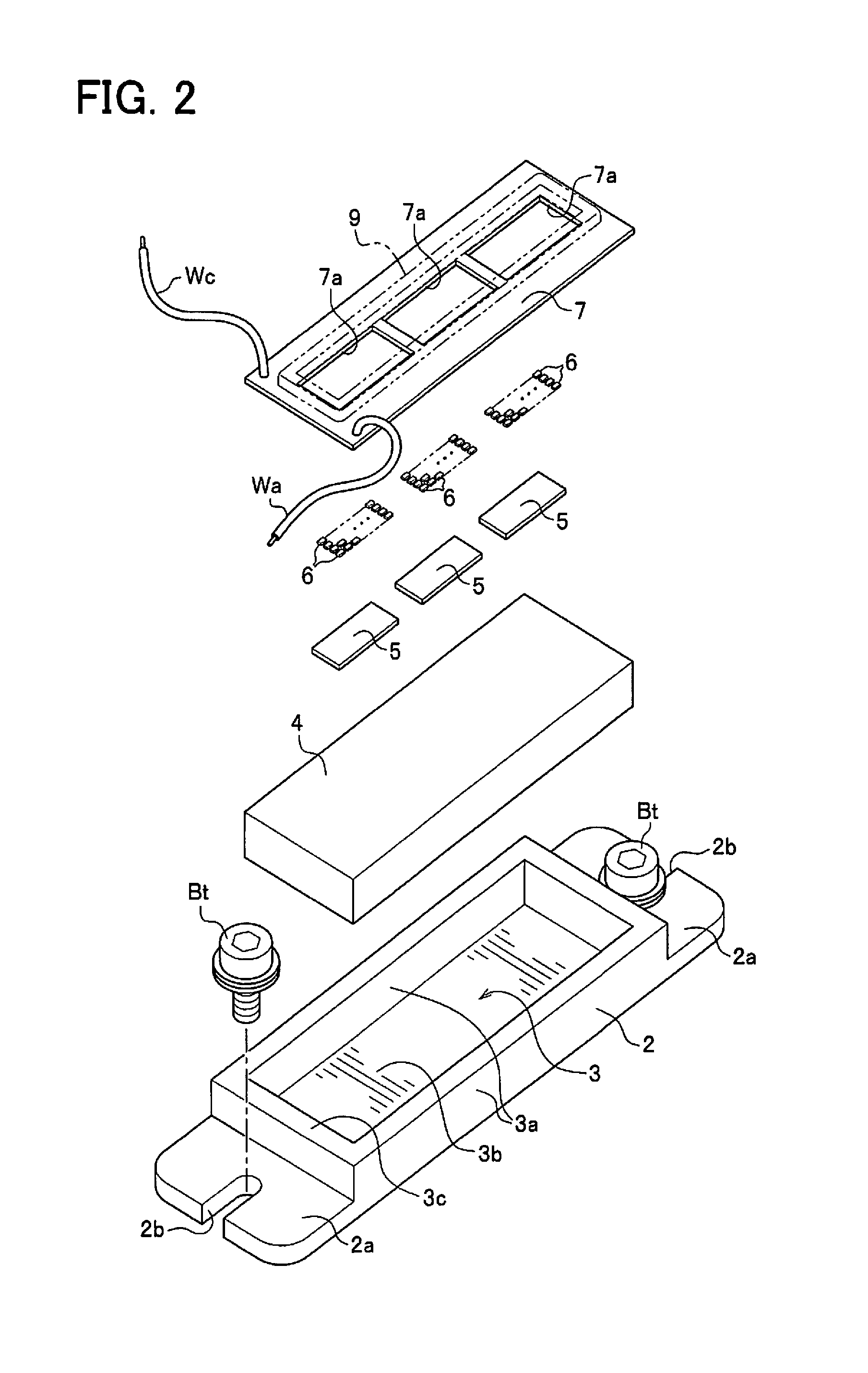
[0031]As shown in FIGS. 1 and 2, a light emitting device 1 has an insulating member 2 equipp...


PUM


Abstract

A light emitting device has a plurality of light emitting elements, a heat spreading member on which the plurality of light emitting elements are mounted, and having a bottom face, an insulating member having a recess that includes side walls and a bottom wall, a top face of the bottom wall being in contact with the bottom face of the heat spreading member, and a circuit board having a circuit that is provided on the heat spreading member and supplies power to the plurality of light emitting elements.

Description

CROSS-REFERENCE TO RELATED APPLICATIONS[0001]This application claims priority to Japanese Patent Applications Nos. 2013-248394 and 2014-190302 filed on Nov. 29, 2013 and Sep. 18, 2014, respectively. The entire disclosure of Japanese Patent Application s Nos. 2013-248394 and 2014-190302 is hereby incorporated herein by reference.BACKGROUND[0002]1. Technical Field[0003]The present disclosure relates to a light emitting device that makes use of a light emitting element, and to a lighting fixture in which this light emitting device is used.[0004]2. Related Art[0005]A package-type light emitting device in which a plurality of light emitting elements (semiconductor light emitting elements) are mounted on a metal substrate or a ceramic substrate in a high-output type of semiconductor light source has been proposed in the past as prior art.[0006]The finished product is incorporated in a lighting fixture in which one or more of these light emitting devices are used, a heat dissipation path i...

Claims


Application Information

Patent Timeline
IPC IPC(8): F21V29/503F21V23/02F21V19/00F21V29/70
CPCF21V29/503F21V19/003F21V23/02F21V29/70F21V19/0055F21V29/505F21V29/74H01L2924/181H01L2224/48137H01L2224/8592H01L2924/19107F21Y2115/10H01L2924/00012
Inventor MIYAIRI, HIROSHIIGARASHI, TAKAYUKIFUJITOMO, MASATOSHIRAHAMA, SATOSHI
Owner NICHIA CORP
Why Eureka
Try Eureka