Turbine shroud segment apparatus for reusing cooling air

a technology of turbine shroud and cooling air, which is applied in the direction of leakage prevention, motors, engine fuctions, etc., can solve the problems of engine energy loss, necessary penalty for engine use of compressed cooling air,

Inactive Publication Date: 2005-05-31
PRATT & WHITNEY CANADA CORP
View PDF23 Cites 114 Cited by
  • Summary
  • Abstract
  • Description
  • Claims
  • Application Information

AI Technical Summary

Problems solved by technology

Since a portion of the energy created by combustion is utilized to drive the compressor and create compressed air, use of compressed cooling air represents a necessary penalty and energy loss for the engine.

Method used


Image

  • Turbine shroud segment apparatus for reusing cooling air
  • Turbine shroud segment apparatus for reusing cooling air
  • Turbine shroud segment apparatus for reusing cooling air

Examples


Embodiment Construction

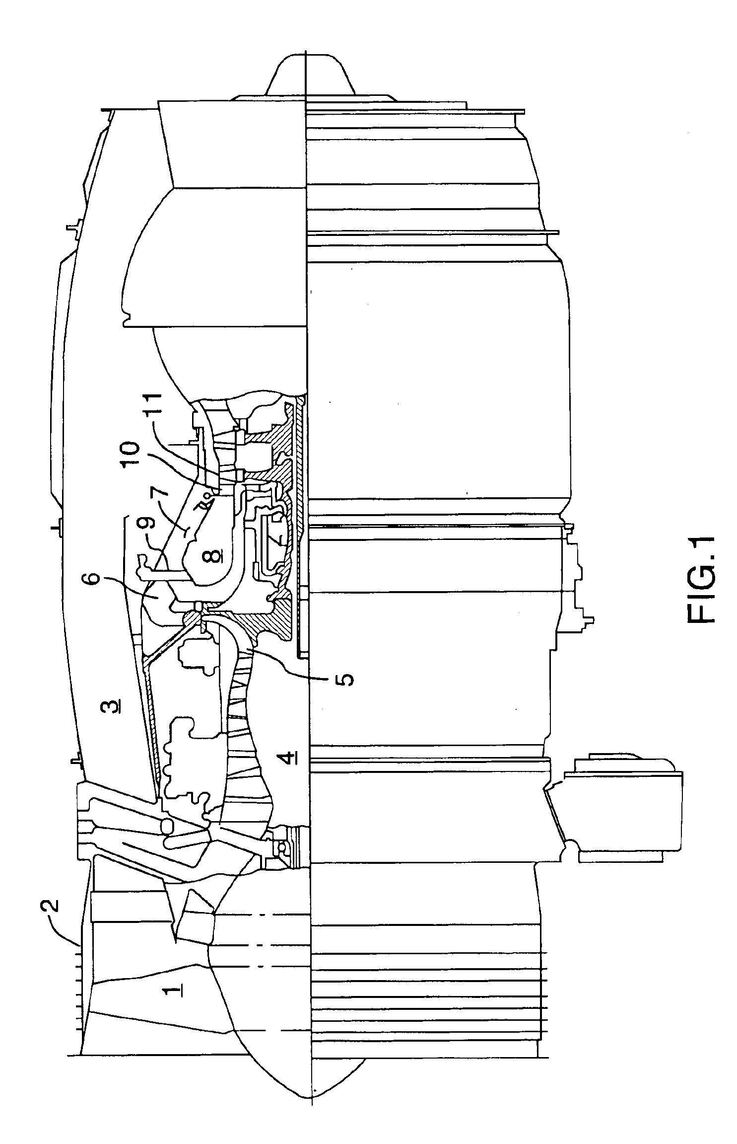
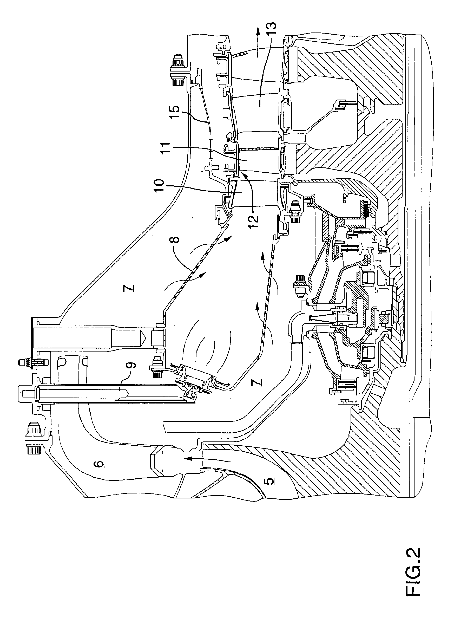
[0017]FIG. 1 shows an axial cross-section through a turbofan gas turbine engine. It will be understood however that the invention is equally applicable to any type of gas turbine engine with a turbine section such as a turboshaft, a turboprop, or auxiliary power unit. Air intake into the engine passes over fan blades 1 in a fan case 2 and is then split into an outer annular flow through the bypass duct 3 and an inner flow through the low-pressure compressor 4 and high-pressure compressor 5. Compressed air exits the compressor 5 through a diffuser 6 and is contained within a plenum 7 that surrounds the combustor 8. Fuel is supplied to the combustor 8 through fuel manifold 9 which is mixed with air from the plenum 7 when sprayed through nozzles into the combustor 8 as a fuel-air mixture that is ignited. A portion of the compressed air within the plenum 7 is admitted into the combustor 8 through orifices in the side walls to create a cooling air curtain along the combustor walls or is ...


PUM


Abstract

A cooled turbine shroud segment for a gas turbine engine, having an axially extending shroud ring segment with an inner surface, an outer surface, an upstream flange and a downstream flange. The flanges mount the shroud ring within an engine casing. A perforated cooling air impingement plate is disposed on the outer surface of the shroud ring between the upstream flange and the downstream flange, with an impingement plenum defined between the impingement plate and the outer surface. Axially extending cooling bores in the ring segment extend between the impingement plenum and an outlet. A trough adjacent the outlet directs cooling air from the outlet towards a downstream stator vane to cool the stator vane.

Description

TECHNICAL FIELD[0001]The invention relates to a gas turbine cooled shroud assembly segment.BACKGROUND OF THE ART[0002]A portion of the core air flow from the compressor section of a gas turbine engine is typically used for air cooling of various components that are exposed to hot combustion gases, such as the turbine blades and turbine shrouds.[0003]Since a portion of the energy created by combustion is utilized to drive the compressor and create compressed air, use of compressed cooling air represents a necessary penalty and energy loss for the engine. Obviously, any minimization of the compressed air portion used for cooling would represent an increase in the efficiency of the engine. While cooled shroud segments are well known in the art, the potential efficiency savings that can be achieved by even small reductions in the amount of secondary cooling air required means that improvement to known devices are consistently sought and highly valued.[0004]It is therefore an object of t...

Claims


Application Information

Patent Timeline
Patent Type & Authority Patents(United States)
IPC IPC(8): F01D25/12F01D25/08F01D11/08F01D9/04
CPCF01D9/04F01D25/12F01D11/08F05D2260/201
Inventor LUCAS, TERRENCEBEDARD, DOMINICDANIEL, AMIRSYNNOTT, REMY
Owner PRATT & WHITNEY CANADA CORP
Why Eureka
Try Eureka