Foot prosthesis having cushioned ankle

a foot prosthesis and ankle technology, applied in the field of prosthetic feet, can solve the problems of difficult to achieve the desired spring compliance and energy return characteristics using a solid ankle block, low-end sach feet do not provide much energy storage and release, etc., to achieve the effect of improving the degree of energy storage and return, and increasing the rigidity of the prosthetic foo

Inactive Publication Date: 2005-05-31
FLEX FOOT
View PDF94 Cites 54 Cited by
  • Summary
  • Abstract
  • Description
  • Claims
  • Application Information

AI Technical Summary

Benefits of technology

[0007]One embodiment of the present invention provides a simple, inexpensive prosthetic foot incorporating an ankle block having selectable compliance and energy return characteristics that may be varied over a wider range to accommodate the different weight, height and activity level of amputees. The ankle block is formed of compressible material having desired compliance and energy return characteristics. The ankle block is sandwiched between a foo...

Problems solved by technology

Specifically, the low end SACH feet do not provide much energy storage and release, as do more sophisticated prosthetic feet.
However, for certain applications it is difficult to attain a desired l...

Method used


Image

  • Foot prosthesis having cushioned ankle
  • Foot prosthesis having cushioned ankle
  • Foot prosthesis having cushioned ankle

Examples


Embodiment Construction

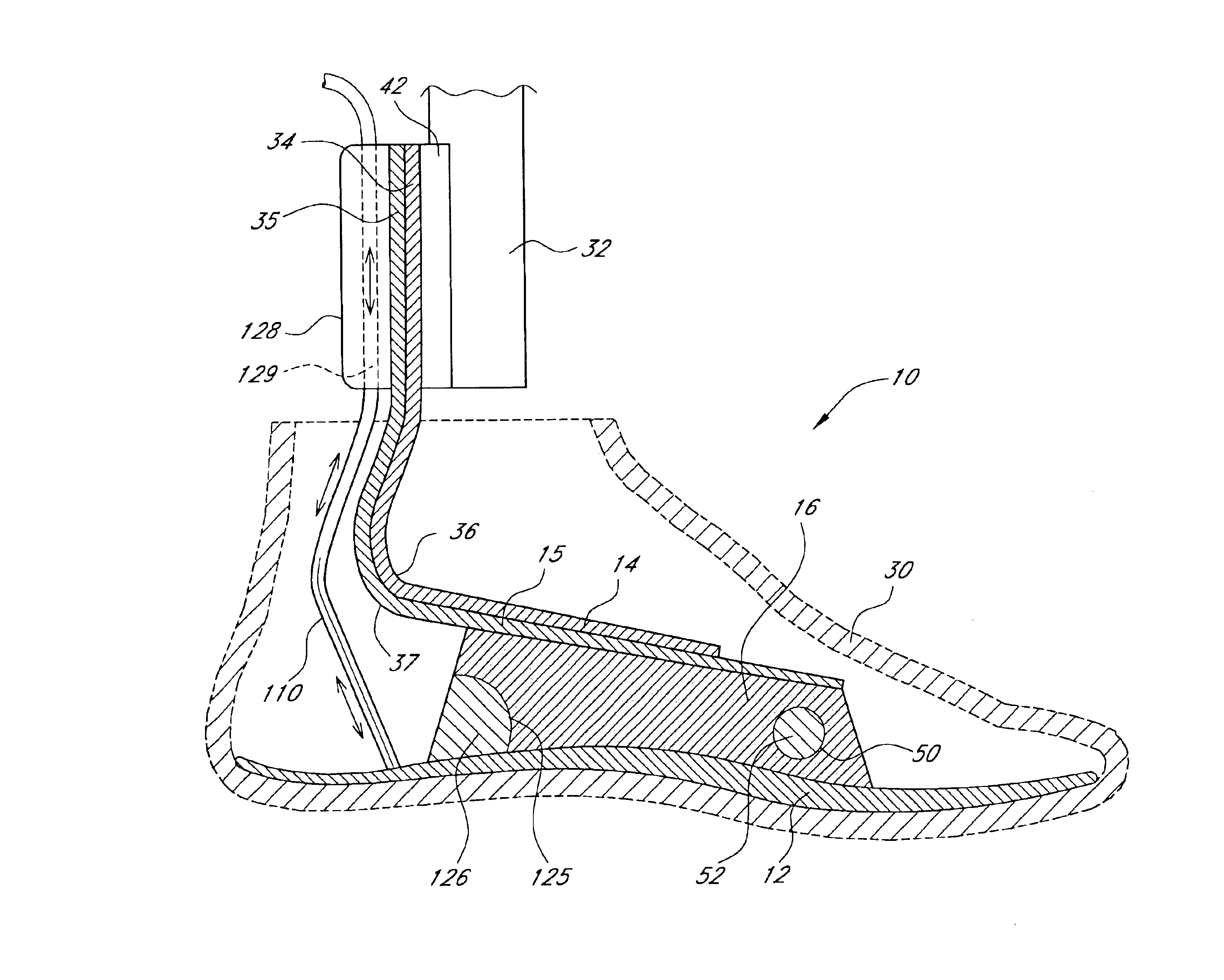
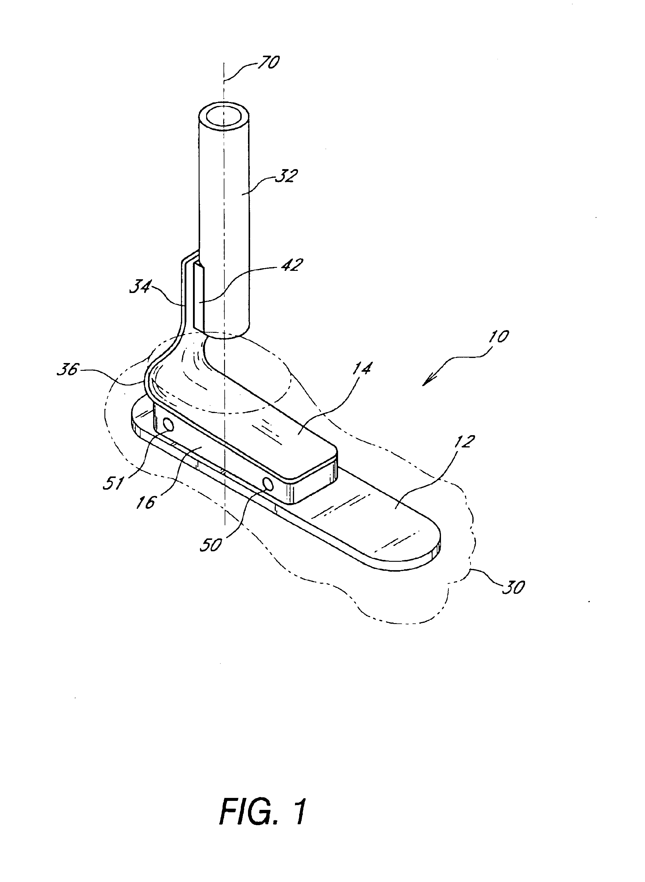
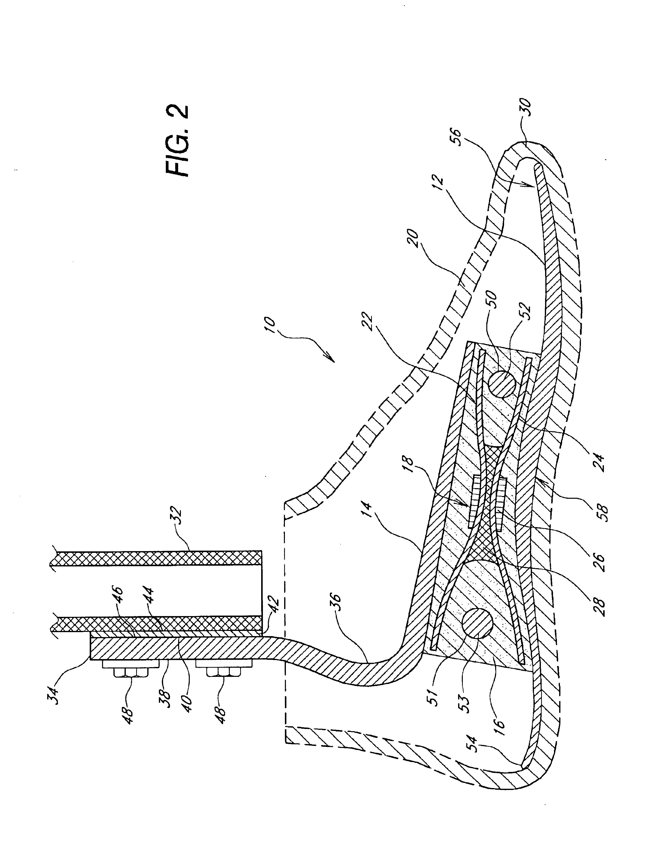
[0048]With reference to FIGS. 1 and 2, a first embodiment of a prosthetic foot 10 of the present invention is shown in a perspective view and a cross-sectional side view, respectively. The prosthetic foot 10 generally comprises a lower foot plate 12, an upper, smaller ankle plate 14, an ankle layer or block 16 made of resilient material, connecting the foot plate 12 to the ankle plate 14, and a spring element 18 embedded within the ankle block 16. The foot plate 12 has a length and width roughly equal to the approximate length and width of the particular wearer's amputated foot and sized to fit within an outer, flexible cosmesis 30, shown in phantom. The ankle plate 14 and the resilient ankle block 16 have approximately the same horizontal cross-sectional size. The ankle plate 14, ankle block 16, and spring element 18 are centered transversely with respect to and are generally positioned over the back half of the foot plate 12. The ankle block 16 is sandwiched between the foot plate...


PUM


Abstract

A simple, inexpensive prosthetic foot is provided incorporating a cushioned ankle including an ankle block formed of a resilient material or bladder having desired compliance and energy return characteristics. The ankle block is sandwiched between a foot element and an ankle element. One or more openings extends through the ankle block with a substantially transverse orientation relative to a forward walking motion. The size and shape of these openings, as well as the insertion of different types of stiffeners therein, provide desired performance characteristics to the ankle block. When the ankle block takes the form of one or more inflatable bladders, the pressure within these bladders is individually controlled by valves to provide desired performance characteristics to different portions of the prosthetic foot. A pump system can also be used to control and generate fluid pressure into these bladders. A preferred pump system generates fluid pressure based upon the movement of the amputee onto two telescoping pylons that are connected to the prosthetic foot.

Description

CROSS-REFERENCE TO RELATED APPLICATIONS[0001]This application is a continuation-in-part of application Ser. No. 09 / 288,869, filed April 9, 1999, now U.S. Pat. No. 6,280,479, which is a continuation-in-part of application Ser. No. 09 / 138,357, filed Aug. 21, 1998, now U.S. Pat. No. 6,206,934, which claims the benefit of U.S. Provisional Application No. 60 / 081,472, filed Apr. 10, 1998. The entireties of both U.S. Pat. Nos. 6,280,479 and 6,206,934 are hereby incorporated by reference.BACKGROUND OF THE INVENTION[0002]1. Field of the Invention[0003]The present invention relates to prosthetic feet and, more particularly, to a simply constructed, low-profile prosthetic foot having enhanced performance characteristics.[0004]2. Description of the Related Art[0005]In the prosthetics market, the conventional SACH (solid-ankle, cushion-heel) foot has been the most widely prescribed artificial foot over the past 35 years. The SACH foot generally includes a solid ankle and cushioned heel foot moun...

Claims


Application Information

Patent Timeline
IPC IPC(8): A61F2/66A61F2/60A61F2/00A61F2/50A61F2/74A61F2/68A61F2/70
CPCA61F2/602A61F2/68A61F2/66A61F2002/748A61F2/6607A61F2002/5001A61F2002/5007A61F2002/501A61F2002/5012A61F2002/503A61F2002/5033A61F2002/5055A61F2002/6614A61F2002/6657A61F2002/6678A61F2002/701A61F2002/74A61F2002/741A61F2002/747A61F2/70A61F2/74A61F2/741A61F2/748
Inventor PHILLIPS, VAN L.POUCHAK, HILLARY
Owner FLEX FOOT
Why Eureka
Try Eureka