Nonwoven webs having improved necking uniformity

Inactive Publication Date: 2005-05-31
KIMBERLY-CLARK WORLDWIDE INC
View PDF42 Cites 32 Cited by
  • Summary
  • Abstract
  • Description
  • Claims
  • Application Information

AI Technical Summary

Benefits of technology

[0025]The present invention is directed to a neckable nonwoven material having cross-directional nonuniformity which facilitates easier necking in the central region of the nonwoven web than in the two edge regions of the nonwoven web, and/or which selectively retards necking in the edge regions relative to the central region. The easier necking in the central region compared to the edge regions results in selectively greater than norm

Problems solved by technology

This results in increased fiber gathe

Method used


Image

  • Nonwoven webs having improved necking uniformity
  • Nonwoven webs having improved necking uniformity
  • Nonwoven webs having improved necking uniformity

Examples


Embodiment Construction

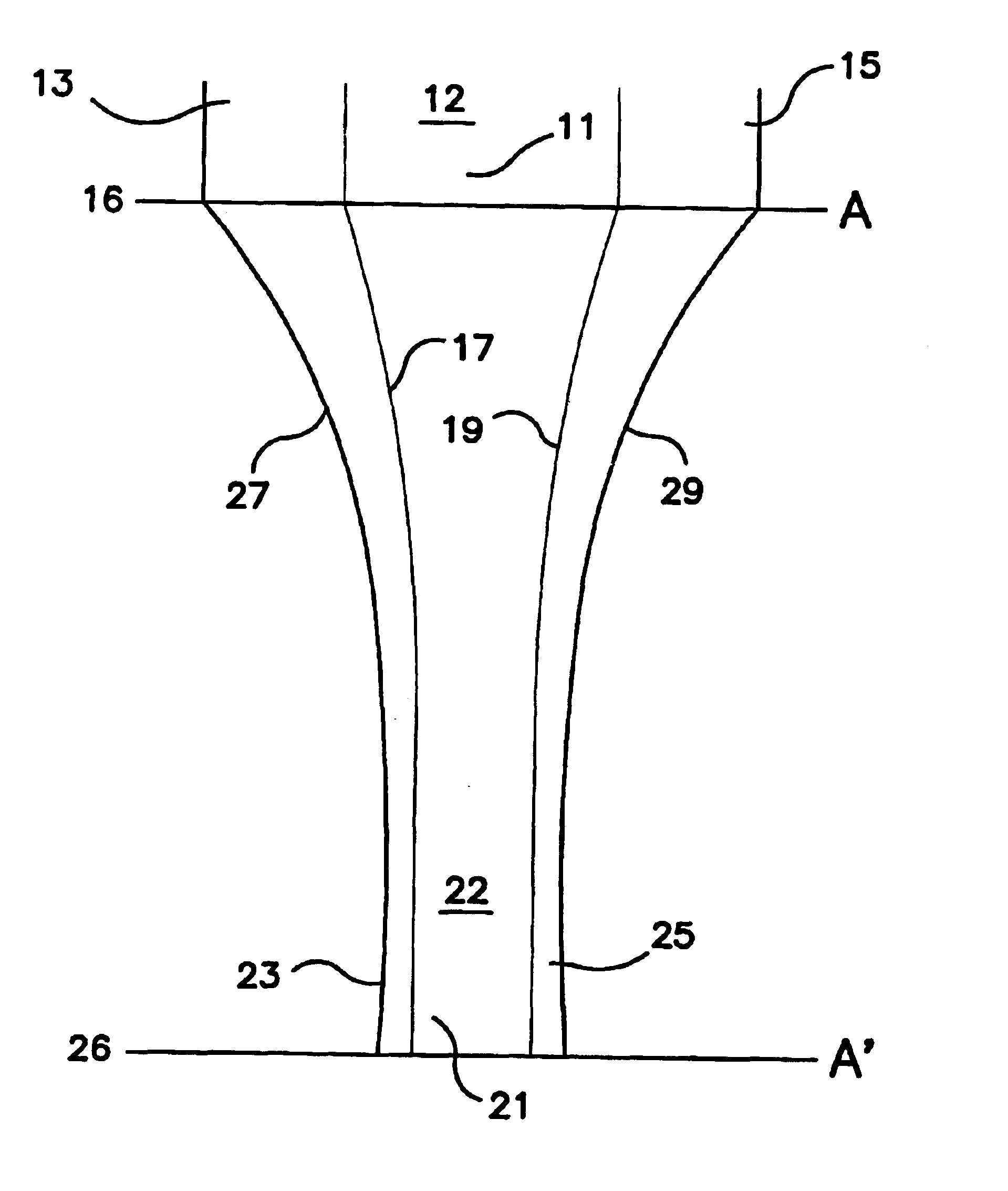
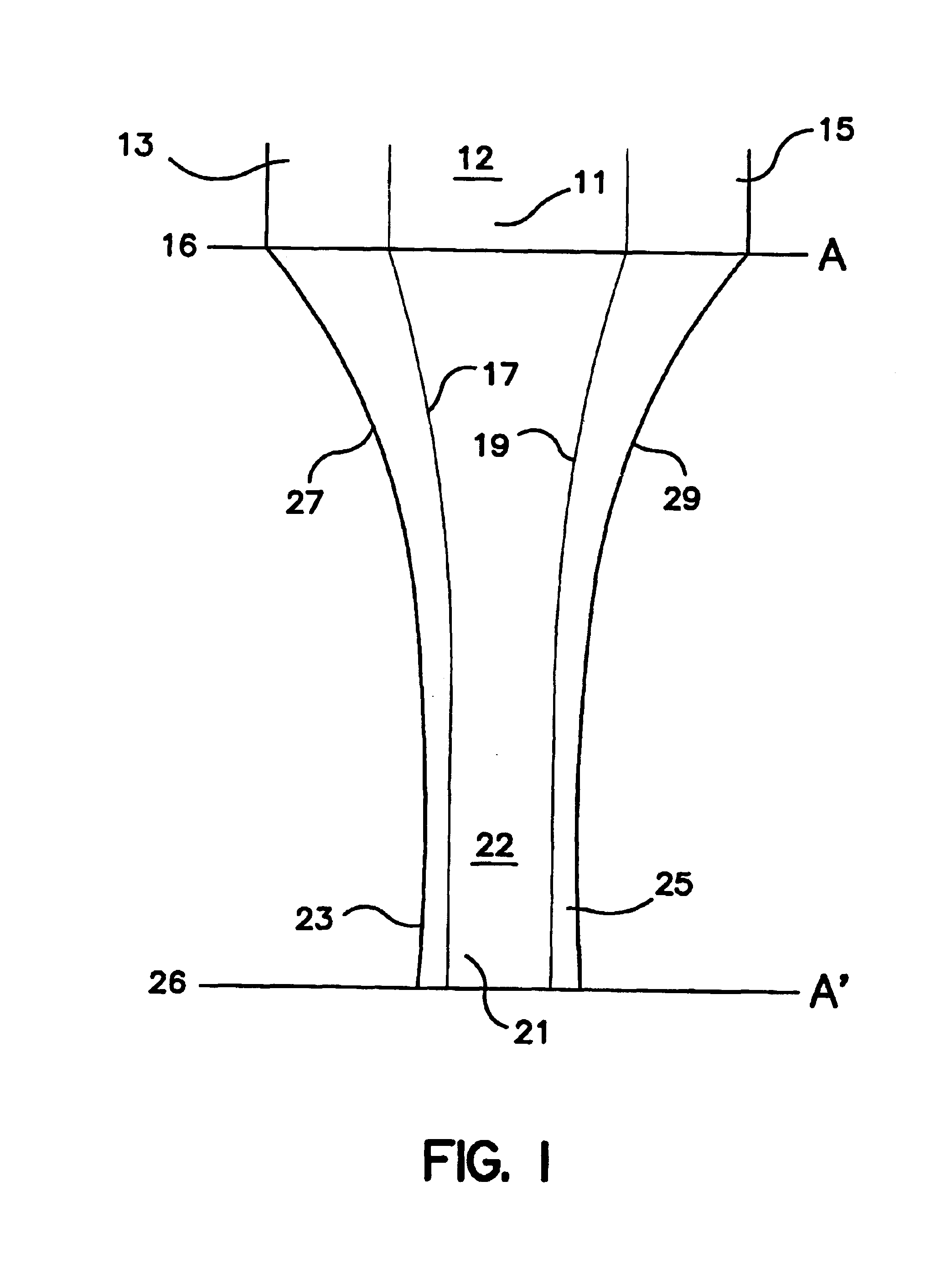
[0032]Referring again to FIG. 1, a neckable nonwoven web 12 has a central region 11 and two end regions 13 and 15. The central region 11 has different physical properties and / or polymer composition than the two end regions 13 and 15, so that the central region has relatively easier necking.

[0033]As explained above, the central region is defined as the central 70% of the lateral width of the nonwoven web, and the two edge regions are defined as the outermost 15% of the lateral width on both sides of the central region. However, this does not mean that the boundaries between the nonwoven fibers which are selectively easier to neck, and the fibers which are harder to neck, must occur precisely at the edges 17 and 19 of the central region. These boundaries may occur inward or outward of the edges 17 and 19 of the central region, so long as the central region is, on average, easier to neck than the two edge regions.

[0034]For instance, the boundaries between fibers which are selectively e...


PUM

PropertyMeasurementUnit
Fractionaaaaaaaaaa
Fractionaaaaaaaaaa
Fractionaaaaaaaaaa

Abstract

A neckable nonwoven web is provided with a central region and two edge regions, the central region being selectively easier to neck than the two edge regions. The nonwoven fibers in the central region have a polymer composition and/or physical properties which differ from the nonwoven fibers in the two edge regions. The selectively easier necking in the central region causes the central region to neck to about the same extent as the two edge regions, which otherwise would experience greater necking than the central region if the starting nonwoven web were completely uniform. Necked nonwoven webs and neck-bonded laminates made using the improved neckable nonwoven web, are also provided.

Description

FIELD OF THE INVENTION[0001]This invention is directed to nonwoven webs which, when exposed to a necking process, exhibit improved necking uniformity across the cross-directional width of the webs. The resulting necked nonwoven webs have more uniform basis weights across their width, compared to conventional necked nonwoven webs which tend to have a lower basis weight in the central region than in both edge regions.BACKGROUND OF THE INVENTION[0002]Necked nonwoven webs, including necked spunbond webs, meltblown webs, combinations, and the like, are often made using a process which is schematically illustrated in FIG. 1. A nonwoven web 12 having a starting width A is passed in its machine direction between a first nip 16, which can be a first pair of nip rollers traveling at a first surface velocity, and a second nip 26, which can be a second pair of nip rollers traveling at a second surface velocity which is faster Man the first surface velocity. The surface velocity difference betwe...

Claims


Application Information

Patent Timeline
IPC IPC(8): B32B27/12B32B5/26B32B5/22D04H13/00B32B5/04B32B25/10D04H1/4374D06C3/06D04H1/4382D04H1/70
CPCB32B5/26B32B27/12D04H13/002Y10T428/24785Y10T428/24777Y10T428/24793Y10T428/24992Y10T428/24479D04H1/4374D04H1/74Y10T442/688Y10T442/637Y10T442/687Y10T442/66Y10T442/60Y10T442/627Y10T442/607Y10T442/684Y10T442/681Y10T442/682Y10T442/68Y10T442/697Y10T442/689Y10T442/635Y10T442/685Y10T442/686Y10T442/601D04H1/43828D04H1/43832D04H1/43835D04H1/4383D04H1/44D04H1/4291D04H3/10D04H13/00
Inventor MORMAN, MICHAEL T.MORELL, CHARLES J.
Owner KIMBERLY-CLARK WORLDWIDE INC
Why Eureka
Try Eureka