Reactive power compensation to minimize step voltage changes and transients

Inactive Publication Date: 2005-05-31
AMERICAN SUPERCONDUCTOR
View PDF8 Cites 23 Cited by
  • Summary
  • Abstract
  • Description
  • Claims
  • Application Information

AI Technical Summary

Benefits of technology

[0005]The invention features a system and approach for minimizing the step voltage change experienced by the utility customer as well minimizing transients imposed on the fundamental waveform of a normal voltage carried on a utility power network when a reactive power source (e.g., capacitor bank) is instantaneously connected to the utility power. The reactive power source is adapted to transfer reactive power of a first polarity (e.g., capacitive reactive power) to the utility power network.
[0008]By transferring reactive power of a second, opposite polarity to the network when the switch is closed, the magnitude of a potentially large step-like change in reactive power introduced from the reactive power source is offset for a period of time, thereby minimizing potential transients which would normally be imposed over the fundamental utility waveform carried on the utility power network. These transients are caused by the generally step-like change in voltage when the reactive power source is connected to the utility power network. Although there are many forms of transients, which can be imposed on the utility waveform, such transients are typically in the form of oscillatory “ringing” imposed over the fundamental waveform. Such ringing can cause among other problems, false switching of power devices and overvoltage failures. In addition, the sudden step voltage change induced by switching the utility reactive device can disrupt sensitive industrial control systems and processes. An overvoltage failure can be catastrophic to customers. In essence, the system “softens” the sharp, step-like introduction of reactive energy from the reactive power source.
[0010]In a preferred embodiment, the controller is configured to activate the reactive power compensation device to transfer reactive power compensation of the first polarity to the utility power network prior to connecting the shunt reactive power source to the utility power network. As stated above, providing reactive power compensation of the second, opposite polarity to the utility power network opposes the abrupt step like introduction to the utility power network of reactive power of the first polarity delivered by the shunt reactive power source. Providing reactive power compensation of the first polarity prior to connecting the shunt reactive power source to the utility power network, allows a significantly greater magnitude of change in reactance when the reactive power compensation of the second polarity is introduced. Furthermore, the reactive power compensation device provides additional voltage support to the system prior to the shunt reactive power source being connected to the utility power network.

Problems solved by technology

A change in magnitude in the desired nominal voltage on the utility power network is detected, and such change results in voltage deviating outside of a utility specified acceptable range.
Such ringing can cause among other problems, false switching of power devices and overvoltage failures.
In addition, the sudden step voltage change induced by switching the utility reactive device can disrupt sensitive industrial control systems and processes.
An overvoltage failure can be catastrophic to customers.

Method used


Image

  • Reactive power compensation to minimize step voltage changes and transients
  • Reactive power compensation to minimize step voltage changes and transients
  • Reactive power compensation to minimize step voltage changes and transients

Examples


Embodiment Construction

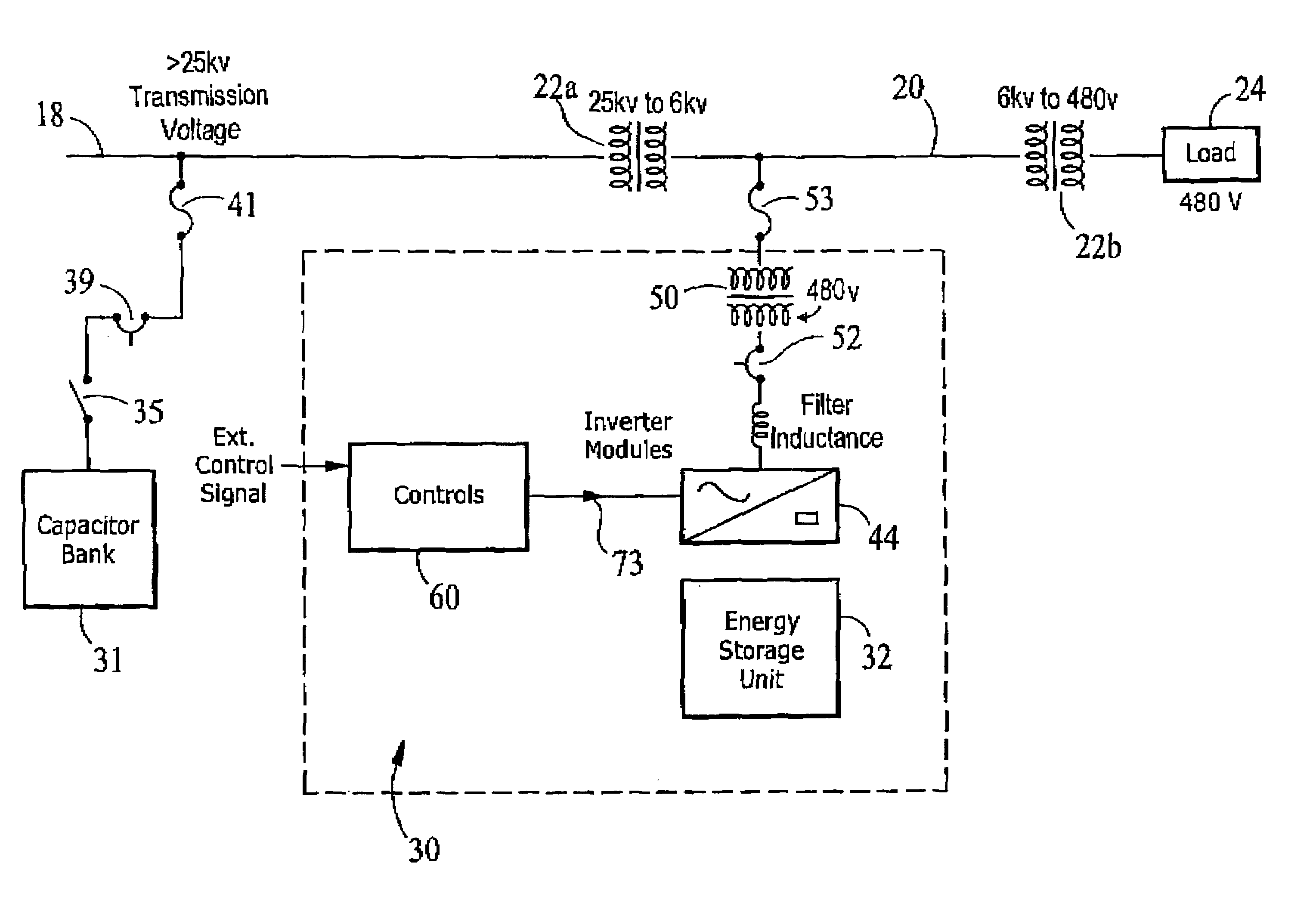
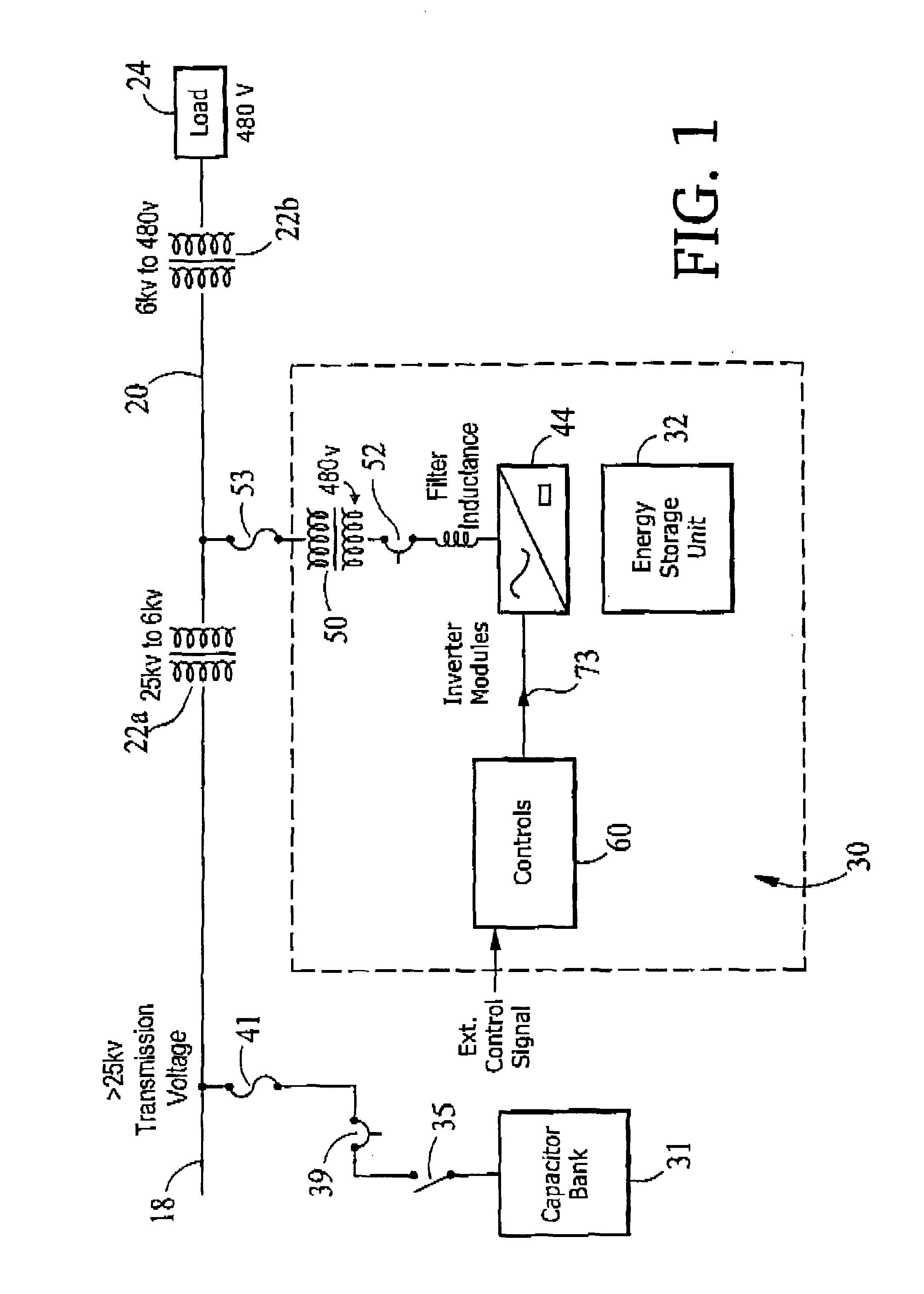
[0023]Referring to FIG. 1, a reactive power compensation system 30 is shown connected in shunt with a distribution line 20 of utility power network. Distribution line 20 is shown connected to a transmission line 18 of the transmission line network through a first transformer 22a, which steps down the higher voltage (e.g., greater than 25 kV carried on transmission line 18 to a lower voltage, here 6 kV. A second transformer 22b steps down the 6 kV to a voltage suitable for a load 24, here 480 V.

[0024]Reactive power compensation system 30 includes an energy storage unit 32, an inverter system 44, and a controller 60, which is used in conjunction with a transmission capacitor bank 31. Energy storage unit 32 may be in a part of a D-SMES module, which is capable, together with inverter system 44, of delivering both real and reactive power, separately or in combination, to distribution line 20. In this embodiment, D-SMES module could be sized at 3.0 MVA and with inverter 44 is capable of ...


PUM


Abstract

The invention features a system and approach for minimizing the step voltage change as seen by the utility customer as well minimizing transients imposed on the fundamental waveform of a normal voltage carried on a utility power network when a reactive power source (e.g., capacitor bank) is instantaneously connected to the utility power. The reactive power source is adapted to transfer reactive power of a first polarity (e.g., capacitive reactive power) to the utility power network. The system includes a reactive power compensation device configured to transfer a variable quantity of reactive power of a second, opposite polarity to the utility power network, and a controller which, in response to the need to connect the shunt reactive power source to the utility power network, activates the reactive power compensation device and, substantially simultaneously, causes the shunt reactive power source to be connected to the utility power.

Description

INCORPORATION BY REFERENCE[0001]This application herein incorporates by reference the following applications: U.S. application Ser. No. 09 / 240,751, which was filed on Jan. 29, 1999, U.S. application Ser. No. 60 / 117,784, filed Jan. 29, 1999, U.S. application Ser. No. 09 / 449,505, entitled “Discharging a Superconducting Magnet”, filed Nov. 24, 1999; U.S. application Ser. No. 09 / 449,436, entitled “Method and Apparatus for Controlling a Phase Angle”, filed Nov. 24, 1999; U.S. application Ser. No. 60 / 167,377, entitled “Voltage Regulation of Utility Power Network”, filed Nov. 24, 1999; U.S. application Ser. No. 09 / 449,375, entitled “Method and Apparatus for Providing Power to a Utility Network”, filed Nov. 24, 1999; and U.S. application Ser. No. 09 / 449,435, entitled “Electric Utility System with Superconducting Magnetic Energy Storage”, filed Nov. 24, 1999.BACKGROUND OF THE INVENTION[0002]This invention relates to electric power utility networks including generating systems, transmission s...

Claims


Application Information

Patent Timeline
IPC IPC(8): H02J3/18
CPCH02J3/1828Y02E40/30
Inventor KEHRLI, ARNOLD P.DIAZ DE LEON, II, JOHN A.FOLTS, DOUGLAS C.
Owner AMERICAN SUPERCONDUCTOR
Why Eureka
Try Eureka