
System and method for single phase transition for multiphase DCDC converters

a converter and multi-phase technology, applied in the direction of electric variable regulation, process and machine control, instruments, etc., can solve the problems of voltage undershoot, incorrect voltage generation of each power stage, and inability to predict voltage transients, etc., to achieve the effect of minimizing transients

Active Publication Date: 2016-07-26
TEXAS INSTR INC
View PDF9 Cites 0 Cited by
  • Summary
  • Abstract
  • Description
  • Claims
  • Application Information

AI Technical Summary

Benefits of technology

This approach minimizes voltage transients during mode transitions, reducing the risk of damage and enabling faster voltage regulation, with the DACs ensuring the output remains constant over time, even during rapid changes.

Problems solved by technology

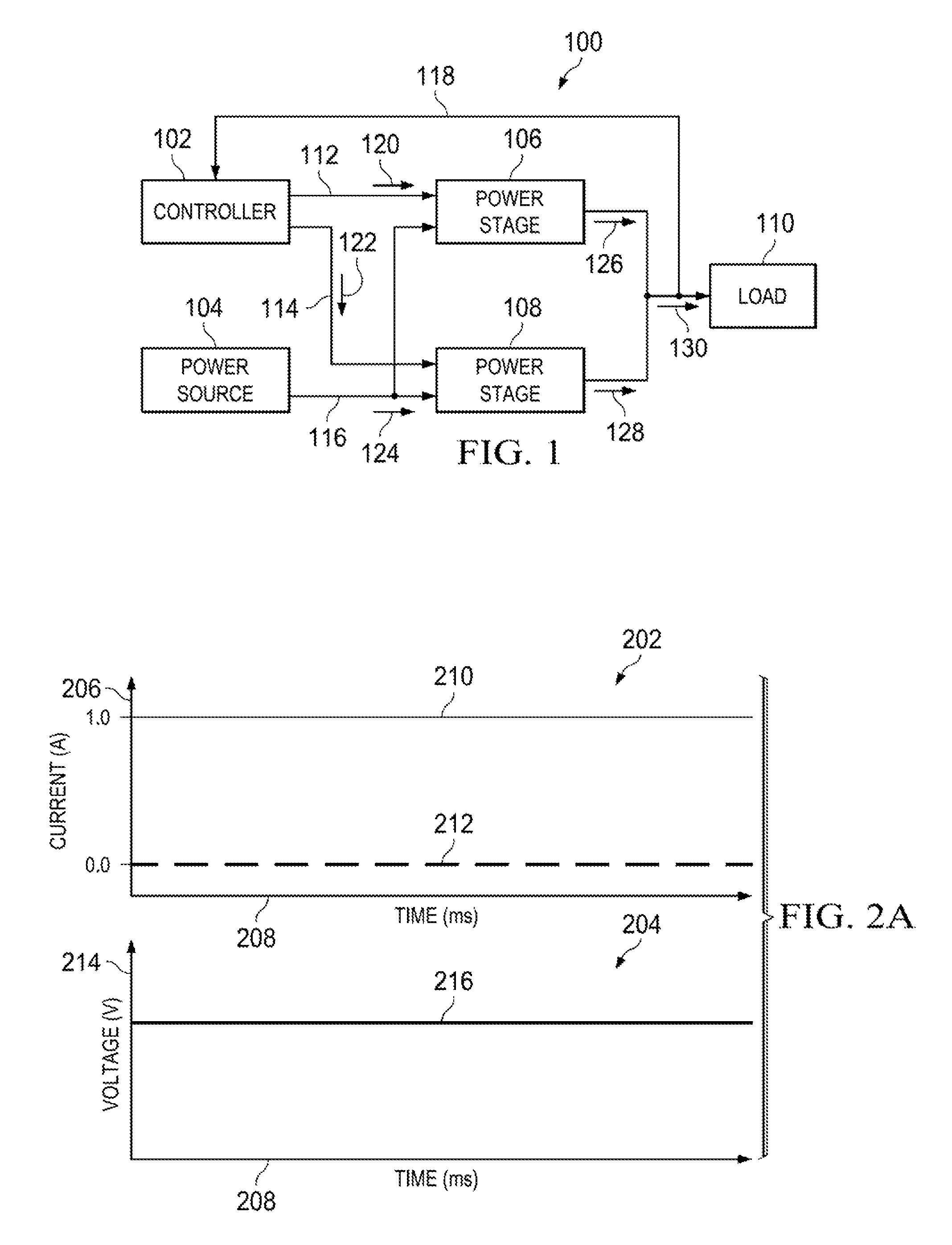
Due to the nonlinearities in the system, the voltage transients cannot be predicted and must be compensated for after they occur by a feedback loop.
In other words, even though the instructions from controller 102 may be correct, the actually produced voltage, and therefore power, from each power stage may be incorrect.
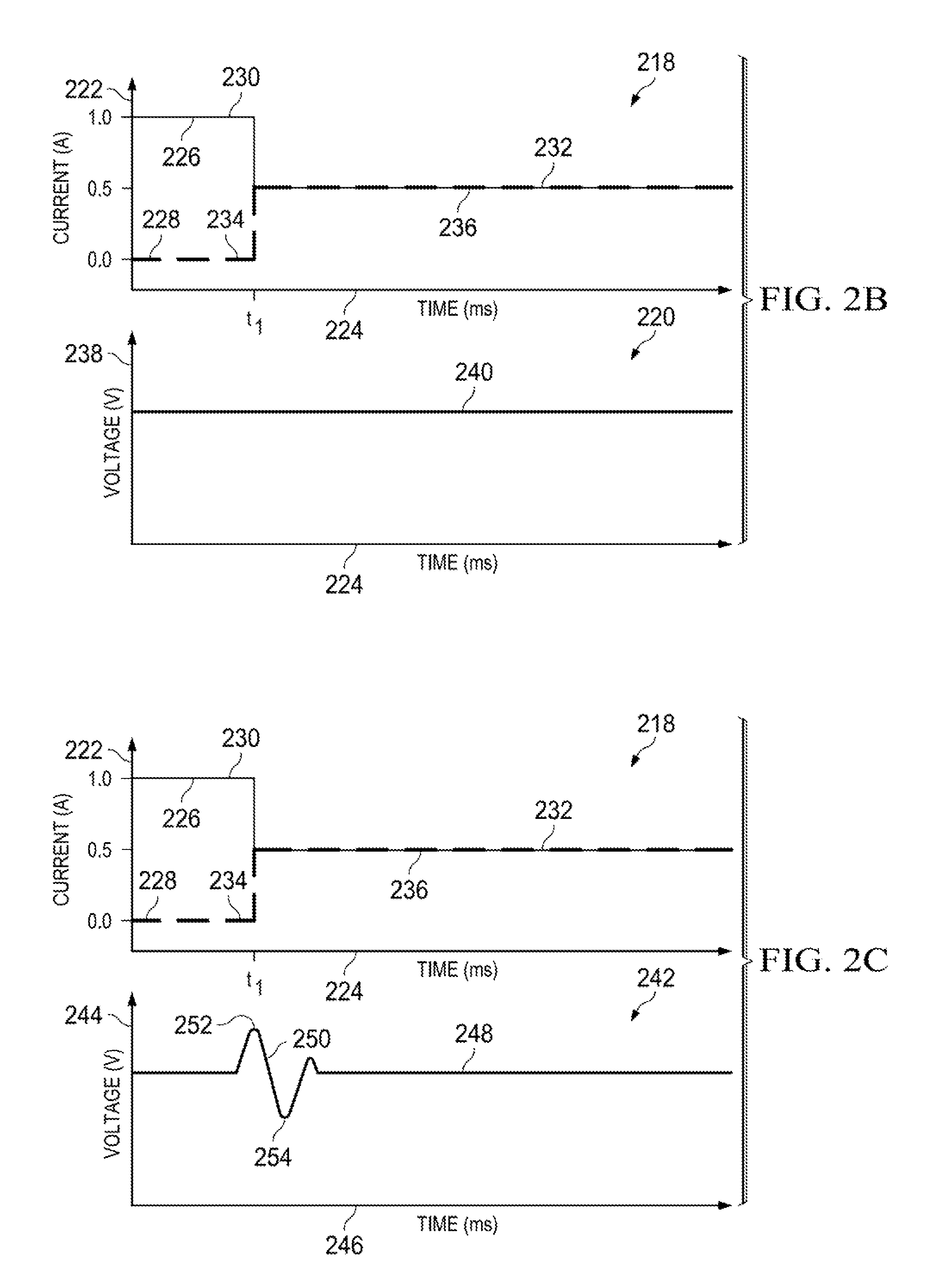
However, the original correction may lead to voltage undershoot 254.
A problem with the conventional system and method for utilizing DC-DC converters is that a transient voltage is created in the output during the transition from two different transfer modes (e.g. the transition from single phase to dual phase or dual phase to single phase operation).
The error in the voltage output takes a relatively long time to correct due to the limited bandwidth of the regulation loop.

Method used


Image

  • System and method for single phase transition for multiphase DCDC converters
  • System and method for single phase transition for multiphase DCDC converters
  • System and method for single phase transition for multiphase DCDC converters

Examples


Embodiment Construction

[0070]The present invention provides a system and method for switching between two different transfer modes of a DC-DC converter, while minimizing a transient in the output voltage.

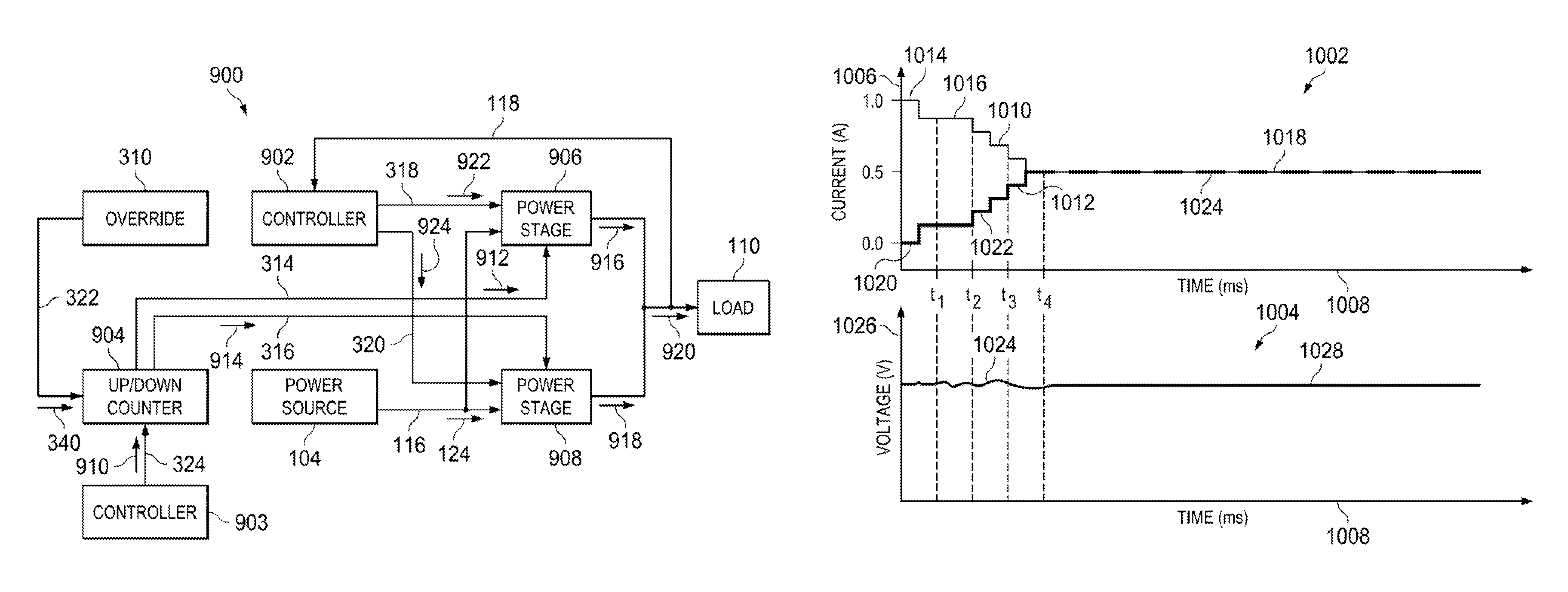
[0071]In accordance with an aspect of the present invention, a DC-DC converter is operable to provide single phase or dual phase power at a constant voltage using two power stages. In single phase mode, an up / down counter is used to turn one power stage on and the second power stage off. In dual phase mode, the up / down counter will turn on the second power stage and increase its current output while concurrently decreasing the current output of the first stage in order to keep the combined current output of both power stages constant.

[0072]The current associated with the output power of one power stage is step-wise increased, whereas the current associated with the output power of another power stage is concurrently and equally step-wise decreased. In other words, the outputs of the two power stages are i...


PUM


Abstract

A DCDC converter includes a controller, an up / down counter, a first power stage and a second power stage. The controller generates an up / down control signal. The up / down counter generates a first power stage control signal and a second power stage control signal based on the up / down control signal. The first power stage generates a first output current at a first phase and at a first voltage based on the first power stage control signal. The second power stage generates a second output current at a second phase based on the second power stage control signal. The up / down counter modifies the first power stage control signal to control the first power stage such that the first output current attenuates from a first power stage output to a secondary first power stage output. The controller can further output a control signal to modify the first voltage of the first power stage.

Description

[0001]The present application claims priority from: U.S. Provisional Application No. 61 / 948,344 filed Mar. 5, 2014, the entire disclosure of which is incorporated herein by reference.BACKGROUND[0002]DC to DC converters are important in portable electronic devices such as cellular phones and laptop computers and are supplied with power from batteries. Such electronic devices often contain several sub-circuits each with its own voltage level requirement different from that supplied by the battery or an external supply (sometimes higher or lower than the supply voltage). A battery's voltage, for example, declines as its stored power is drained. Switched DC to DC converters offer a method to increase voltage from a partially lowered battery voltage thereby saving space instead of using multiple batteries to accomplish the same thing.[0003]Electronic switch-mode DC to DC converters transform one DC voltage level to another, by storing the input energy temporarily and then releasing that ...

Claims


Application Information

Patent Timeline
Patent Type & Authority Patents(United States)
IPC IPC(8): H02M1/00H02M3/158H02M3/156H02M1/08G06F1/26H02J1/10
CPCH02M3/156G06F1/26H02M1/08H02M3/1584H02J1/102
Inventor BAYER, ERICHKIRCHNER, JOERGLUEDERS, MICHAEL
Owner TEXAS INSTR INC
Learn More