Method and circuit for stop of signals quantized using noise-shaping
a technology of noise shaping and signal quantization, applied in the direction of local circuits, digital transmissions, electrical apparatus, etc., can solve the problems of degrading the performance of inband systems, achieve the effect of reducing inband disturbance, simple implementation, and reducing inband transients
- Summary
- Abstract
- Description
- Claims
- Application Information
AI Technical Summary
Benefits of technology
Problems solved by technology
Method used
Image
Examples
example 1
Traditional Noise-Shaper Stop
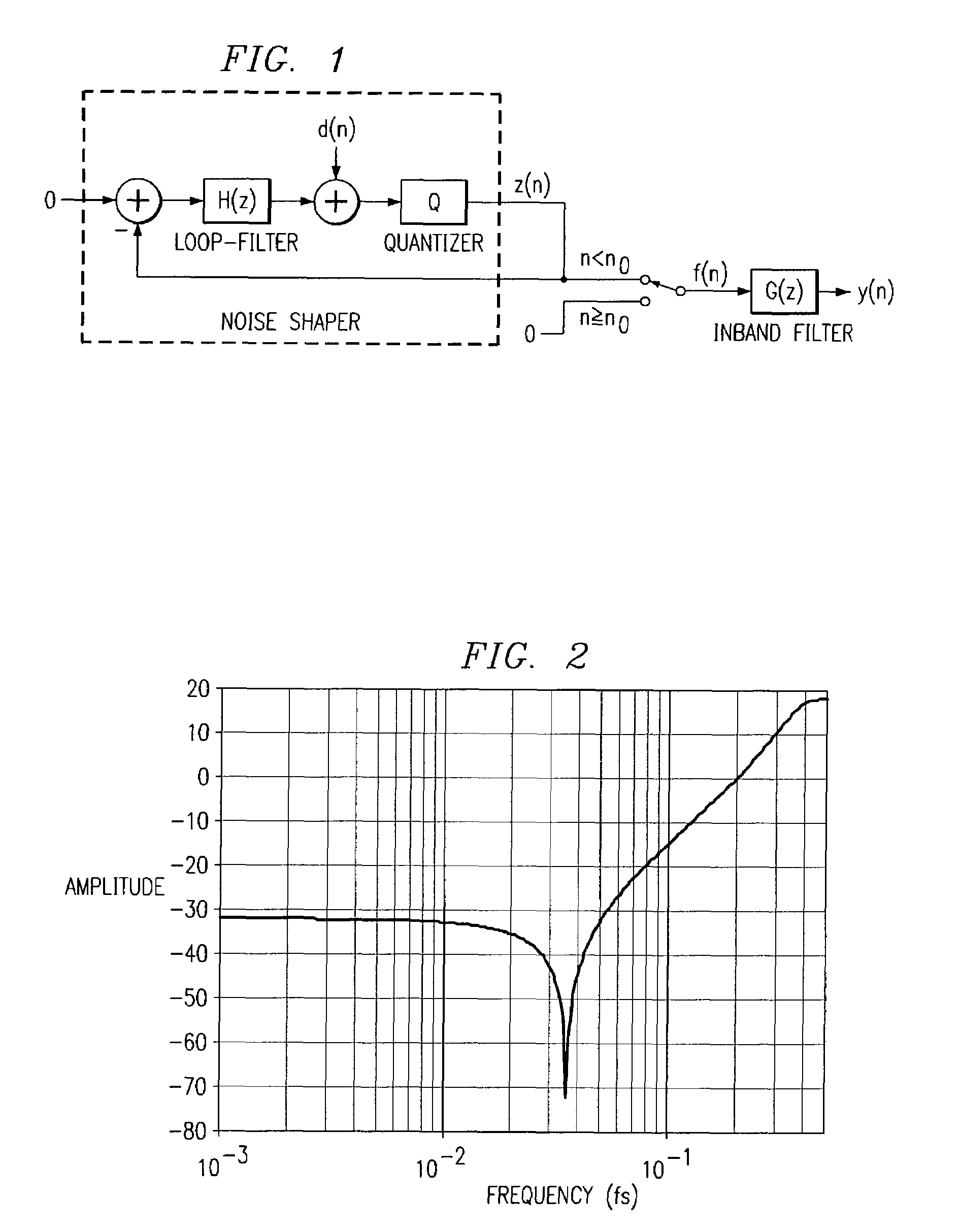
[0046]A 2nd order noise-shaper is made using the topology shown in FIG. 1. The amplitude of the noise transfer function (NTF) is shown in FIG. 2. The dither signal d(n) is white noise with a triangular probability density function in the interval [−1;1]; and the quantization step size in the quantizer is 1.
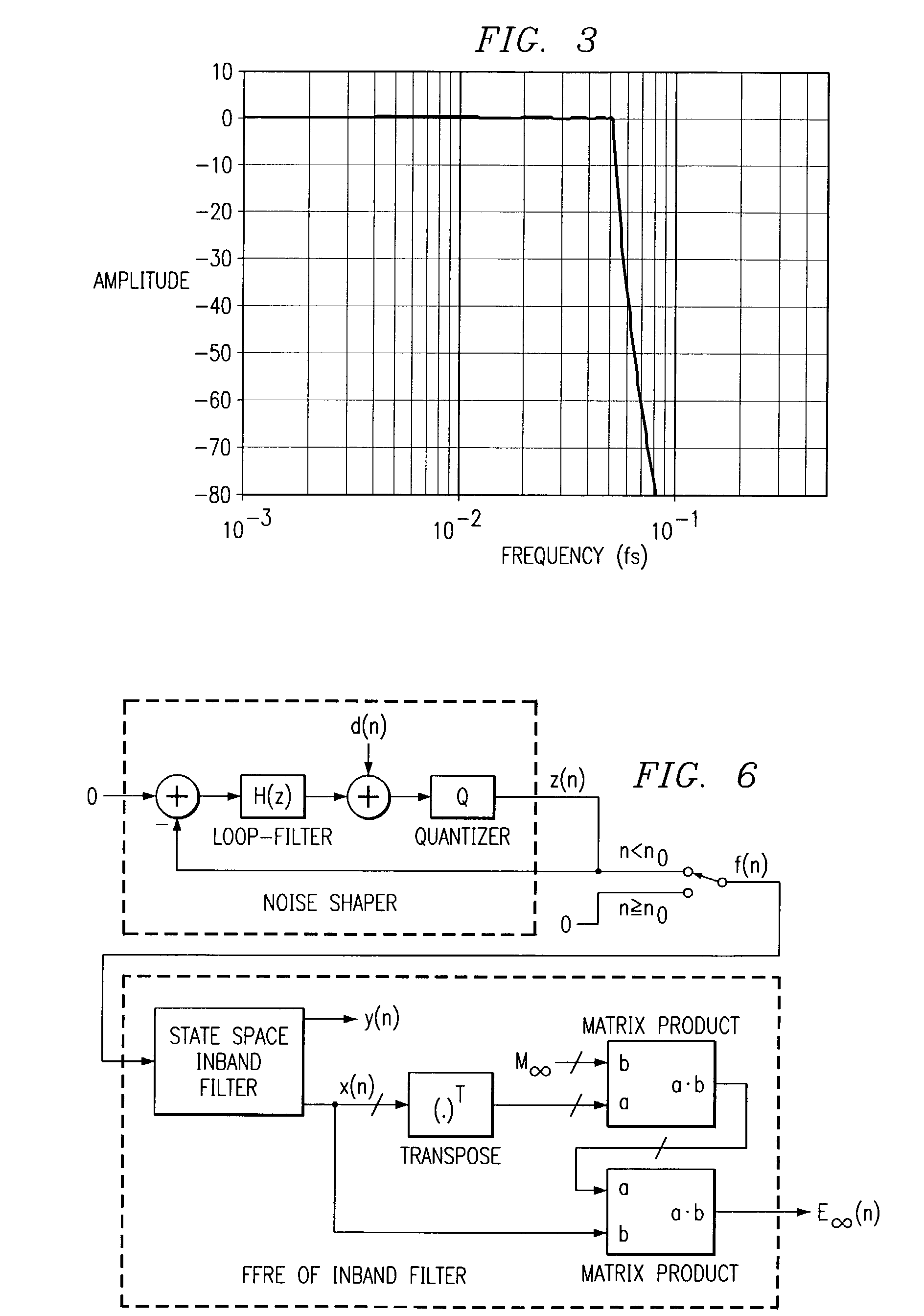
[0047]FIG. 3 is a plot diagram illustrating the amplitude characteristic of the inband filter G(z) shown in FIG. 1 for a 10th order Chebyshev filter having a cutoff frequency of 1 / 20 of the sampling frequency fs.
[0048]FIG. 4 is a waveform diagram illustrating the quantized output signal f(n) shown in FIG. 1 for n0=0.
[0049]FIG. 5 is a waveform diagram illustrating the signal y(n), that is an inband filtered version of the quantized output signal f(n). A significant transient can be seen at n=n0=0 due to the stop of the noise-shaped zero. The noise before n=n0=0 is the spectrally shaped noise from the quantization.
Future Filter Response Energy
[0050]A f...
example 2
Future Inband Trancient Enegry Calculation
[0057]In the present example is used the same noise-shaper and inband filter characteristic as in Example 1. Also here we have n0=0. The FFRE of the inband filter E∞(n) can be calculated for each sample, assuming that the future filter input is zero—if the noise-shaped signal is stopped.
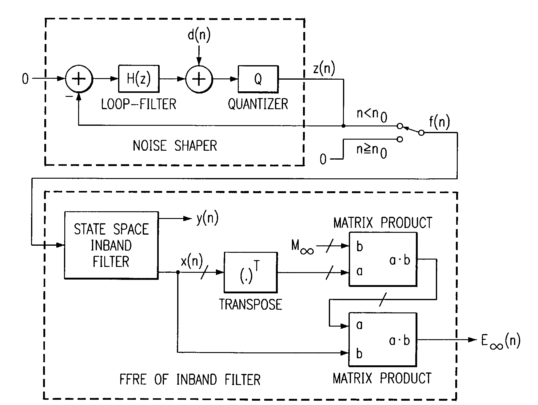
[0058]The FFRE calculation for the inband filter is done using equation (5), where the constant matrix MN=M∞ is found from (10) using the inband filter state-space representation. At FIG. 6, the FFRE calculation is shown in block diagram form corresponding to equation (5).
[0059]Now running the system, stopping the noise-shaped signal at n0=0 gives the quantized output signal f(n) shown in FIG. 7, which has an inband filtered content y(n) as shown in FIG. 8 and FIG. 9 as seen before in Example 1. The FFRE of the inband filter E∞(n), of the quantized output signal is shown in FIG. 10 and FIG. 11.
[0060]The distribution of the FFRE is given by the noise-shaper ch...
example 3
Noise-Shaper Stop Synchronized by a Detector
[0066]The system at FIG. 13 is simulated with a detector filter identical to the inband filter from Example 2, i.e. an amplitude characteristic as shown in FIG. 3. The transient energy limit is EL=0.01 and the noise-shaper stop is initiated at n=n0=0. With these settings, the noise-shaped output signal f(n) looks as shown in FIG. 16 and FIG. 17. It is noted that the noise-shaped signal is stopped at n=3, which is the first sample where n≧n0 and E∞(n)L. FIG. 18 and FIG. 19 show resultant plots of E∞(n). The FFRE of the detector filter at the sample (n=3), where the noise-shaped signal is stopped, is E∞(3)=0.0058, corresponding to the energy of the inband transient shown in FIG. 20 and FIG. 21 for n≧3. A significant reduction of the inband transient is seen by a comparison of FIG. 20 and FIG. 8.
[0067]FIG. 22 is a histogram showing the distribution of the inband transient energy corresponding to 4·106 noise-shaper stops for this system 10 usi...
PUM
 Abstract
Description
Claims
Application Information
 - R&D
- Intellectual Property
- Life Sciences
- Materials
- Tech Scout
- Unparalleled Data Quality
- Higher Quality Content
- 60% Fewer Hallucinations
Browse by: Latest US Patents, China's latest patents, Technical Efficacy Thesaurus, Application Domain, Technology Topic, Popular Technical Reports.
© 2025 PatSnap. All rights reserved.Legal|Privacy policy|Modern Slavery Act Transparency Statement|Sitemap|About US| Contact US: help@patsnap.com


