Method and disk drive for improving head position accuracy during track following through real-time identification of external vibration and monitoring of write-unsafe occurrences

a technology of track following and head position accuracy, applied in the field of disk drives, can solve the problems of significant competitive disadvantage, substantial reduction in the operation performance of the disk drive in the presence of vibration, and increase the likelihood, so as to attenuate the effect of external vibration and improve the head position accuracy

Inactive Publication Date: 2005-05-31
WESTERN DIGITAL TECH INC
View PDF17 Cites 123 Cited by
  • Summary
  • Abstract
  • Description
  • Claims
  • Application Information

AI Technical Summary

Benefits of technology

[0006]The present invention may be embodied in a method for improving head position accuracy in a disk drive during track following of concentric data storage tracks on a rotating disk's storage surface through real-time identification of external vibration and monitoring of write-unsafe (WUS) occurrences. In the method, a seek operation to a predetermined data storage track is performed. After the seek operation, the predetermined data storage track is followed using a servo control loop that has a nominal gain and that is responsive to a position error signal (PES) generated during track following. After waiting a vibration detection delay period after the seek operation to the predetermined data storage track, occurrences of the PES exceeding a WUS limit are counted to generate a WUS limit exception count. Also, a property of a variance is determined from a predetermined number of temporally accumulated spectral power values, within a predetermined frequency band, generated from the PES during track following. If the WUS limit exception count exceeds a first threshold, and if the property of the variance exceeds a second threshold, the gain of the servo control loop, within the predetermined frequency band, is increased from the nominal gain to a vibration gain, to attenuate the effect of external vibration on the position of the head during track following.

Problems solved by technology

Market demand for increased storage capacity has pushed disk drive designers to increase the TPI of disk drives, thereby increasing the likelihood that an external vibration may undesirably force the disk drive's read / write head over an adjacent track during track following.
A substantial reduction in a disk drive's operational performance in the presence of vibration may be a significant competitive disadvantage.

Method used


Image

  • Method and disk drive for improving head position accuracy during track following through real-time identification of external vibration and monitoring of write-unsafe occurrences
  • Method and disk drive for improving head position accuracy during track following through real-time identification of external vibration and monitoring of write-unsafe occurrences
  • Method and disk drive for improving head position accuracy during track following through real-time identification of external vibration and monitoring of write-unsafe occurrences

Examples


first embodiment

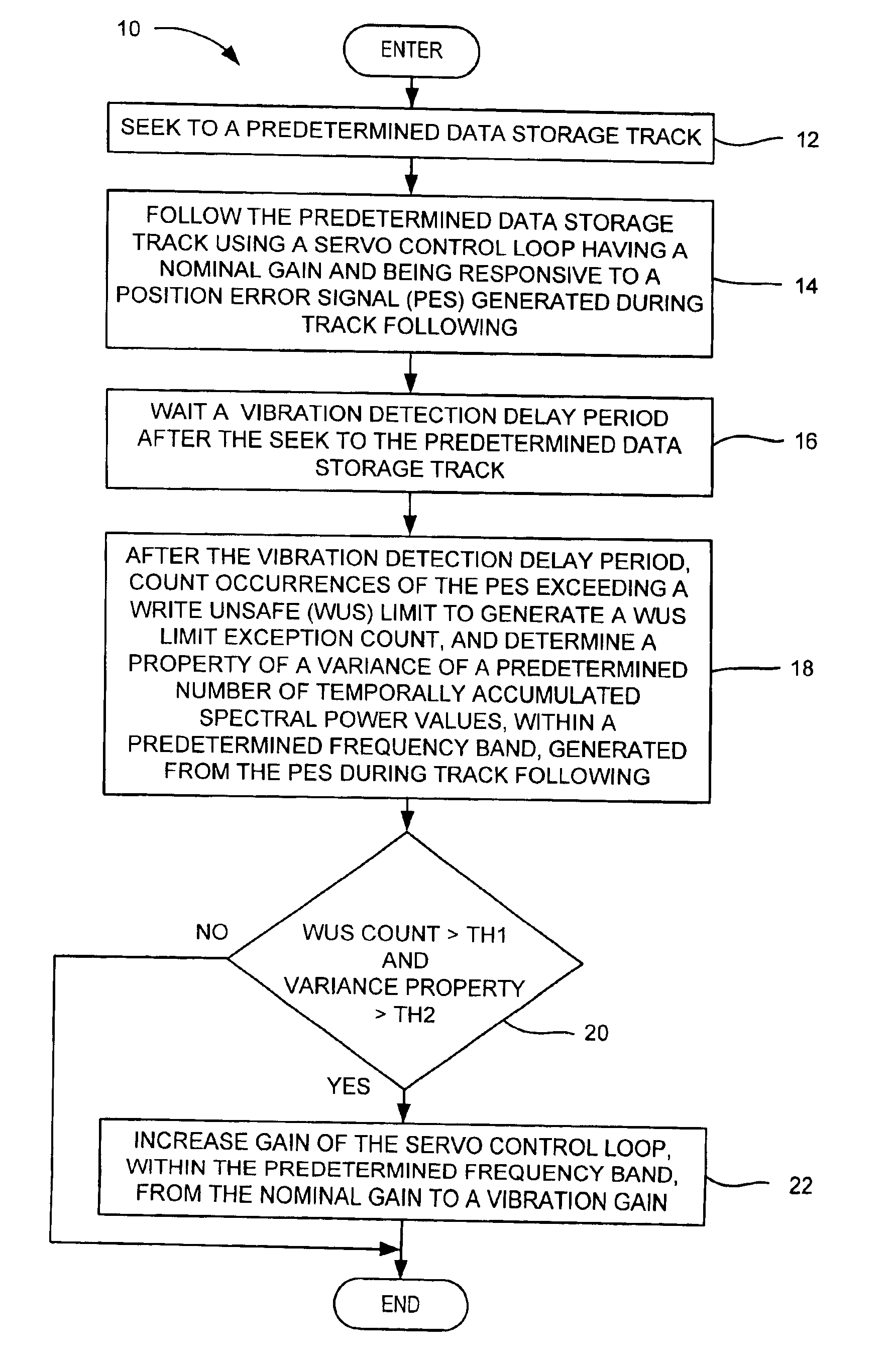
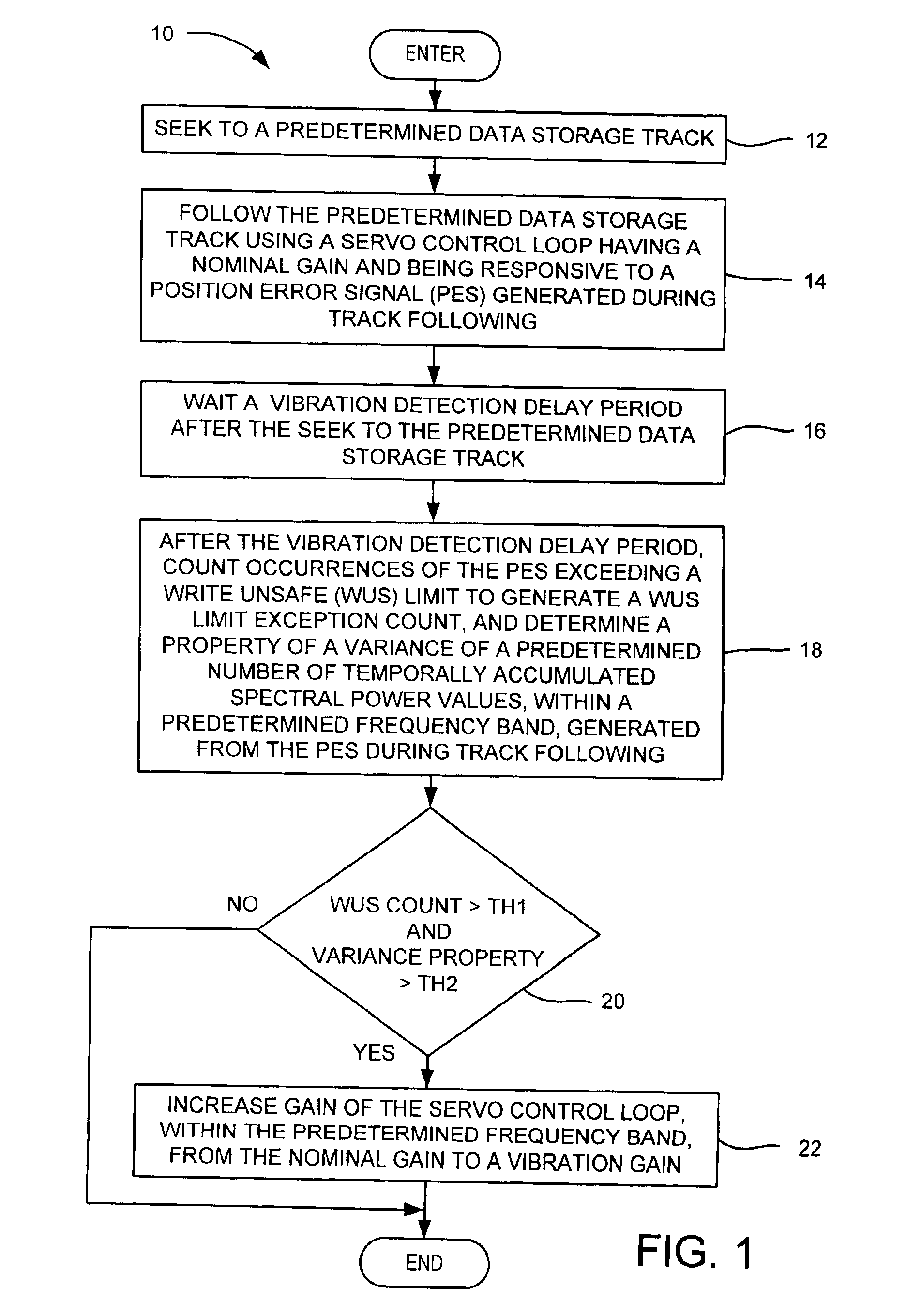
[0025]In the servo control loop 40 (FIG. 3A), a vibration condition is detected using a WUS detector 74, a band pass filter 76, an excursion calculator 78, and vibration logic 79. The WUS detector compares the PES 42 with the WUS limit 48 and counts occurrences of WUS limit exceptions. The band-pass filter has a predetermined frequency band and generates spectral power values 80 from the PES. The spectral power values are accumulated over a time window 82 that includes temporally accumulated spectral power values 1 through N (e.g., N=104), as shown in FIG. 6A. A variance of the spectral power values is calculated for the values falling within the window. The variance is a statistical mean of the squares of variations from the mean of a distribution of the spectral power values falling within the window. The calculated variance is compared with a baseline variance value to generate an excursion. The excursion is basically a difference between the calculated variance value and the bas...

second embodiment

[0030]In the servo control loop 40 (FIG. 3B), the gain of the servo control loop may be increased by switching between a first compensator 70A and a second compensator 70B. The first compensator may be a nominal gain compensator and the second compensator may be a higher vibration gain compensator. When both thresholds, TH1 and TH2, are met, the vibration logic 79 changes the state of the switches, SW 1 and SW2, from position A to position B, to switch from use of the first compensator 70A to use of the second compensator 70B, thus increasing the gain of the servo control loop.

[0031]With reference to FIG. 7, for a given frequency band, the band-pass filter may be used both for the vibration detection and the add-on compensation as shown by the band-pass filter / add-on compensator 75. Because the band-pass filter may be implemented by firmware in the control system 52, the band-pass filter firmware code and parameters may be used in both the detection state and the vibration state by ...


PUM

PropertyMeasurementUnit
frequencyaaaaaaaaaa
frequencyaaaaaaaaaa
vibration time periodaaaaaaaaaa

Abstract

A method is disclosed for improving head position accuracy in a disk drive during track following of concentric data storage tracks through real-time identification of external vibration and monitoring of write-unsafe (WUS) occurrences. In the method, after a seek operation to a predetermined data storage track, the track is followed using a servo control loop having a nominal gain and responsive to a position error signal (PES). After waiting a vibration detection delay period, occurrences of the PES exceeding a WUS limit are counted generating a WUS limit exception count. Also, a property of a variance is determined from spectral power values generated from the PES during track following. If the WUS limit exception count exceeds a first threshold, and if the property of the variance exceeds a second threshold, the nominal gain is increased to a vibration gain within a frequency band, to attenuate the effect of external vibration.

Description

BACKGROUND OF THE INVENTION[0001]1. Field of the Invention[0002]The present invention relates to disk drives, and more particularly, to a technique for improving head position accuracy during track following.[0003]2. Description of the Prior Art and Related Information[0004]In order to remain competitive, disk drive manufacturers must continually provide increased data storage capacity while rigidly controlling disk drive manufacturing cost. One key to increased storage capacity is increased track density, often expressed as tracks per inch or TPI. Market demand for increased storage capacity has pushed disk drive designers to increase the TPI of disk drives, thereby increasing the likelihood that an external vibration may undesirably force the disk drive's read / write head over an adjacent track during track following. A substantial reduction in a disk drive's operational performance in the presence of vibration may be a significant competitive disadvantage.[0005]Accordingly, there ...

Claims


Application Information

Patent Timeline
Patent Type & Authority Patents(United States)
IPC IPC(8): G11B5/596G11B5/55
CPCG11B5/59627G11B5/5582G11B5/59694
Inventor YI, LISONG, YANBINSPAULDING, DAVID A.BUTT, ARAFAT M.MCNAB, ROBERT J.NGUYEN, DAVID D.
Owner WESTERN DIGITAL TECH INC
Why Eureka
Try Eureka