Image forming apparatus

a technology of image forming apparatus and image carrier, which is applied in the direction of electrographic process apparatus, instruments, optics, etc., can solve the problems of adversely affecting image quality, the potential difference between the image carrier and the casing or similar member adjoining it, and the initial charge of the image carrier is apt to suffer serious hazard, etc., to reduce the charge potential of the image carrier, reduce the fall of image density, and prolong the life of the image carrier

Inactive Publication Date: 2005-05-31
RICOH KK
View PDF11 Cites 23 Cited by
  • Summary
  • Abstract
  • Description
  • Claims
  • Application Information

AI Technical Summary

Benefits of technology

[0017]It is a first object of the present invention to provide a developing device capable of lowering the charge potential of an image carrier to thereby extend the life of the image carrier, reduce the fall of image density and irregular image density ascribable to the variation of a development potential, and obviate excessive toner deposition, an image forming process unit using the developing device, and an image forming apparatus using either one of the developing device and image forming process unit.
[0018]It is a second object of the present invention to provide a developing device capable of increasing the developing ability to implement desirable development even when the charge potential of an image carrier is lowered, and reducing background contamination ascribable to toner of opposite polarity even when a difference between a bias for development and the background potential of the image carrier varies over a range of from 0 V to 200 V, an image forming process unit using the developing unit, and an image forming apparatus using either one of the developing device and image forming process unit.
[0019]It is a third object of the present invention to provide a developing device capable of lowering the amount of charge of a developer to thereby increase a developing ability while reducing hazard to the developer, reducing the influence of the potential variation of an image carrier, and effecting exposure with a quantity of light having low energy to thereby extend the life of the image carrier, an image forming process unit using the developing unit, and an image forming apparatus using either one of the developing device and image forming process unit.

Problems solved by technology

The image carrier is apt to suffer from serious hazard when initially charged.
Further, it is likely that a potential difference between the image carrier and a casing or similar member adjoining it exceeds a discharge start voltage.
Discharge between the image carrier and the member adjoining it would adversely effect image quality.
A decrease in development potential, however, gives rise to the following problems.
As a result, the low-potential system is more likely to lower image density or render image density irregular than the conventional high-potential system.
However, an increase in γ value makes image density more susceptible to the influence of the variation of the development potential, compared to the conventional high-potential system.
Moreover, an increase in γ value is apt to deposit an excessive amount of toner on the image carrier because the magnet brush contains a sufficient amount of toner.
Excessive toner deposition is therefore apt to bring about background contamination, toner scattering at the time of transfer, smearing of a line image and other defects.
A developer is subjected to mechanical hazard due to its contact with magnetic grains or a metering member.
More specifically, it is likely that an additive coating the individual grain is buried in the grain and lowers the fluidity or the charging ability of the grain.
It is therefore extremely difficult to maintain desirable image quality.
The image carrier is subjected not only to the previously mentioned optical fatigue, but also to serious hazard at the time of initial charging.
However, the problem is that a low-potential process is susceptible to the variation of the surface potential of the image carrier.

Method used


Image

  • Image forming apparatus
  • Image forming apparatus
  • Image forming apparatus

Examples


first embodiment

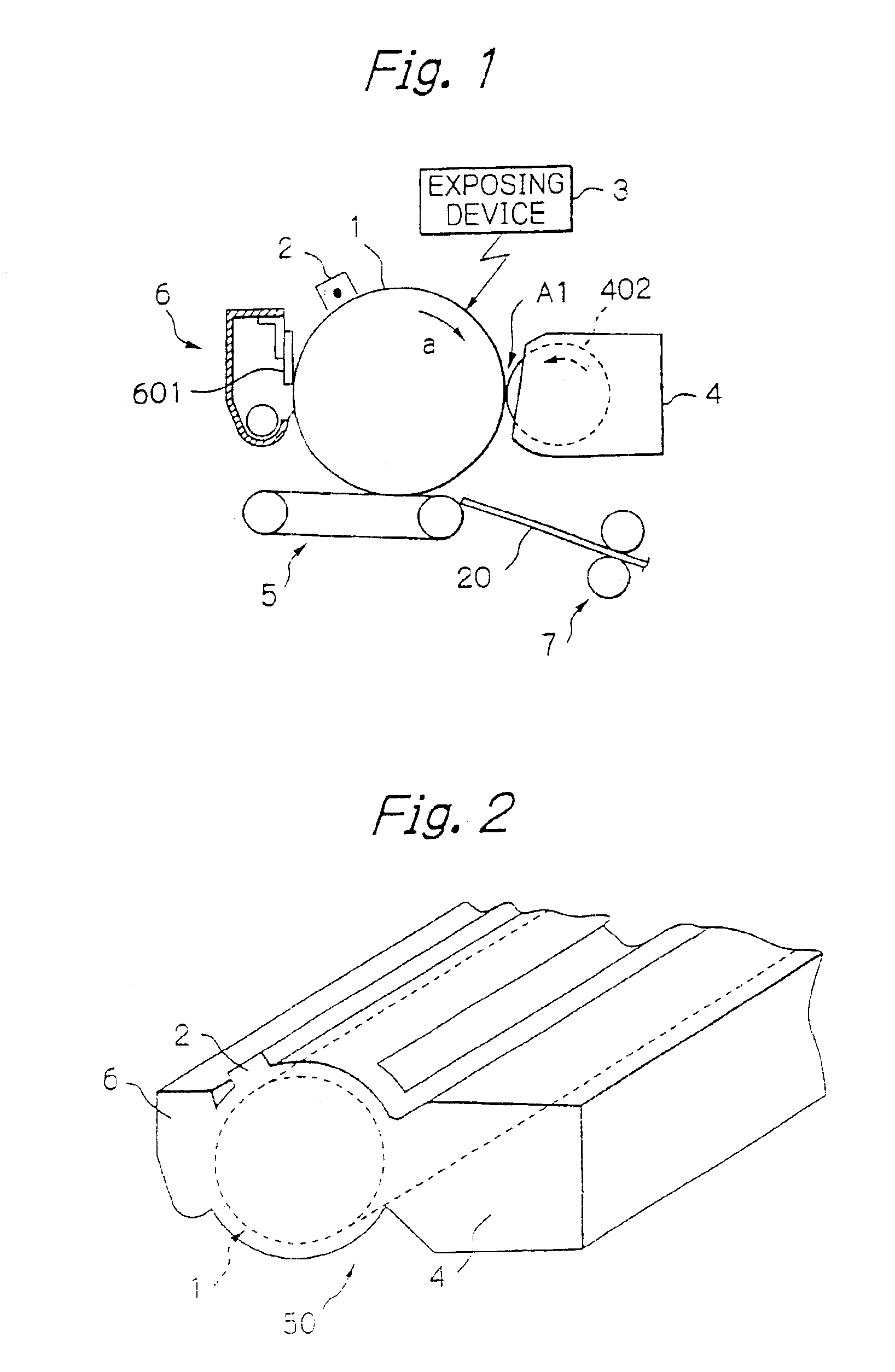
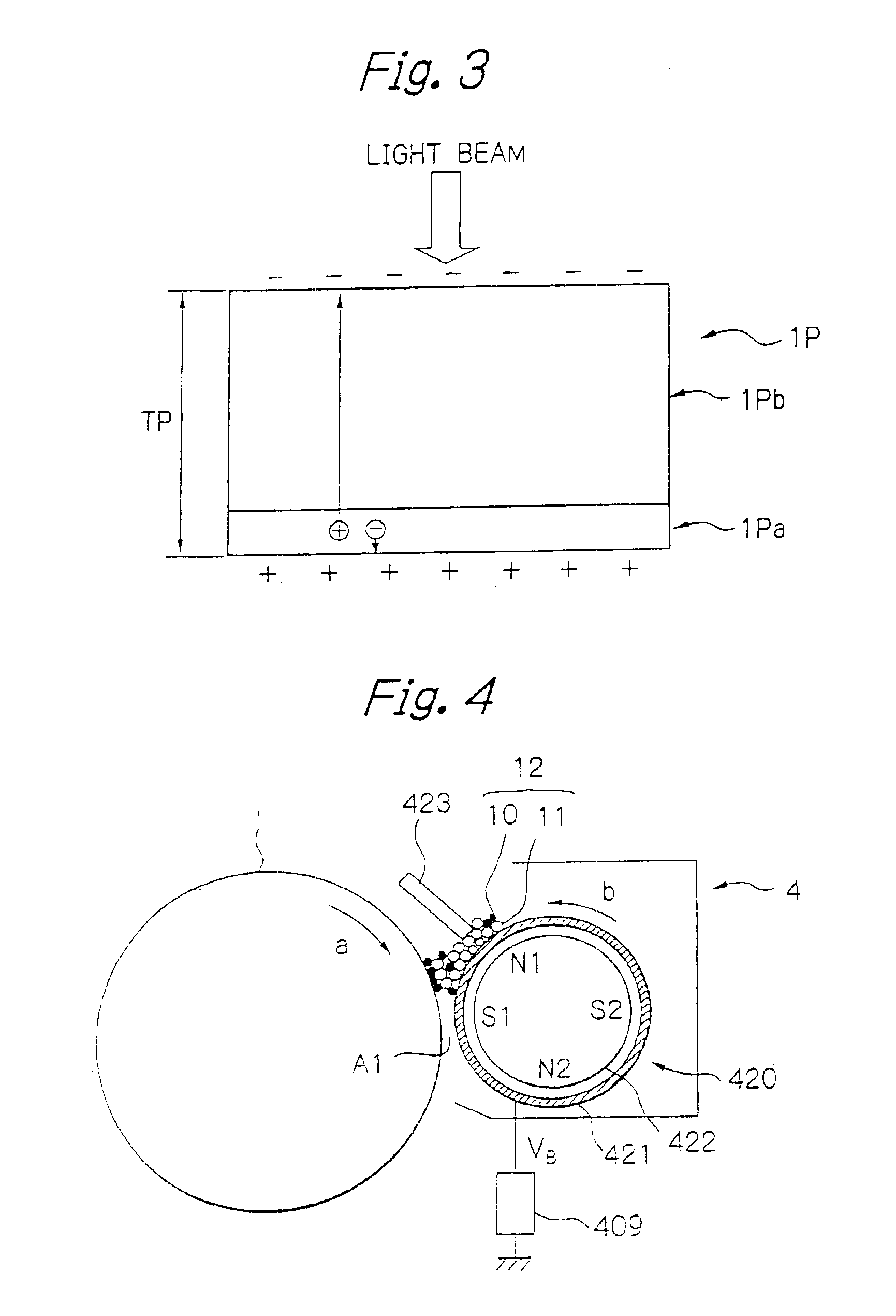
[0108]Referring to FIG. 1 of the drawings, an image forming apparatus embodying the present invention and mainly directed toward the first object stated earlier will be described. This embodiment is implemented as an electrophotographic laser printer by way of example. As shown, the laser printer includes an image carrier implemented as a photoconductive drum 1. Arranged around the drum 1 are a charger 2, an exposing device 3, a developing device 4 using a toner and carrier mixture, an image transferring device 5, and a cleaning device 6.

[0109]The charger 2 uniformly charges the surface of the drum 1 to preselected polarity. The exposing device 3 scans the charged surface of the drum 1 with a laser beam in accordance with image data, thereby forming a latent image on the drum 1. The developing device 4 includes a developing roller 420 and develops the latent image with charged toner deposited on the sleeve 402 to thereby form a corresponding toner image. The image transferring devic...

second embodiment

[0164]This embodiment is also mainly directed toward the first object stated earlier and practicable with the same arrangements as the previous embodiment. In the illustrative embodiment, the developing device 4 uses a single-ingredient type developer, i.e., toner. The developing roller or toner carrier 402 conveys a toner layer deposited thereon and causes it to contact a latent image formed on the drum 1.

[0165]Specifically, as shown in FIG. 21, the casing 401 stores the toner 10 and accommodates an agitator or agitating means 411 rotatable for agitating the toner 10. The toner 10 is therefore mechanically fed to a feed roller 412 also received in the casing 401. The feed roller 412 is formed of foam polyurethane or similar flexible material and can easily retain the toner 10 in cells having a diameter of 50 μm to 500 μm. The feed roller 412 has relatively low hardness ranging from 10° to 30° (JIS (Japanese Industrial Standards) A scale) and can uniformly contact the developing rol...

third embodiment

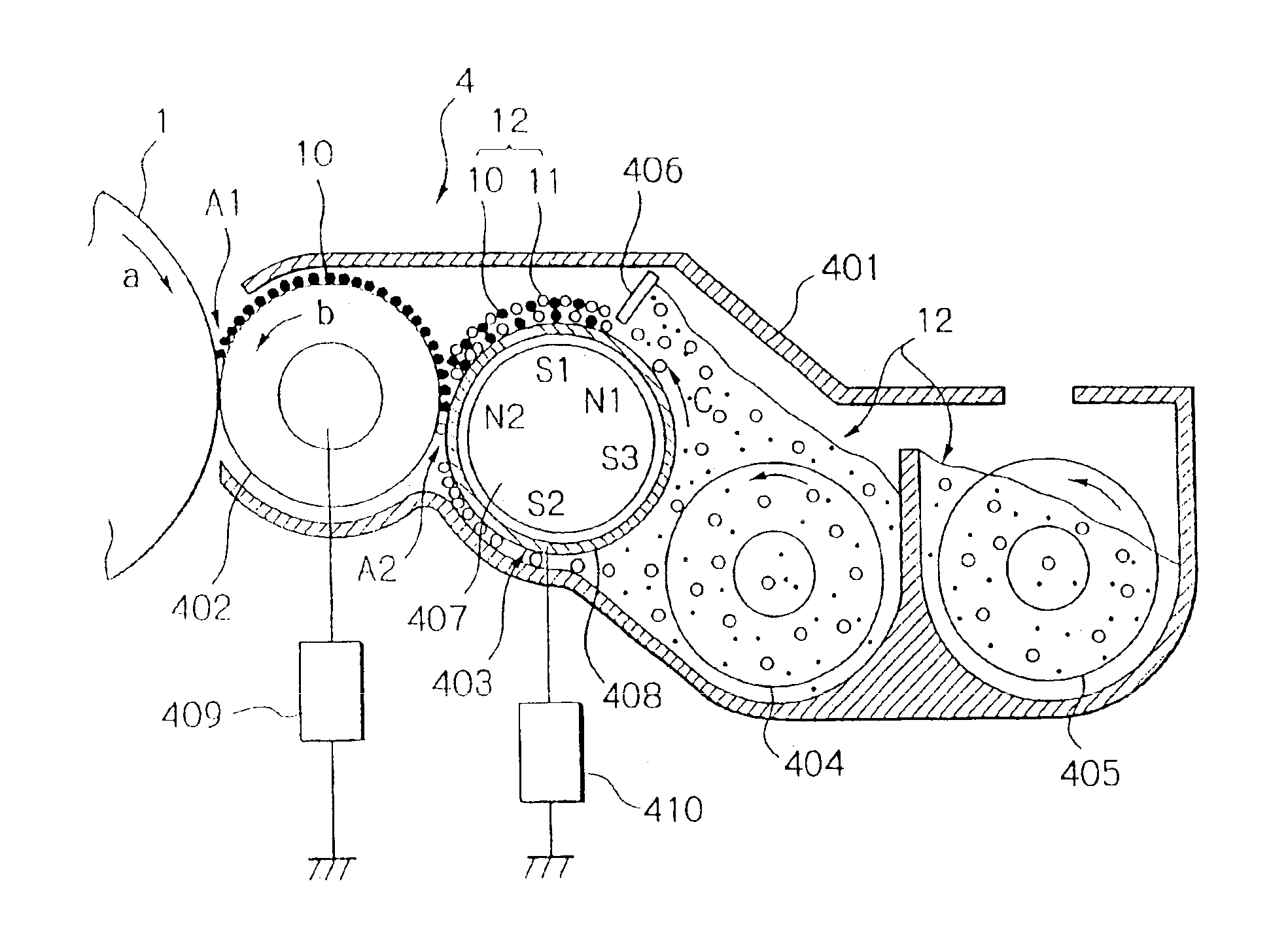
[0184]FIG. 27 shows a third embodiment of the present invention. This embodiment is also mainly directed toward the first object stated earlier and practicable with the same arrangements as the first embodiment. As shown in FIG. 28, the drum 1, charger 2, developing device 4 and cleaning device 6, for example, may also be constructed into a process cartridge removably mounted to the printer body. As shown in FIG. 29, This embodiment differs from the first embodiment in that the feed member for feeding the toner to the developing roller 402 is implemented as a magnet brush roller.

[0185]Specifically, as shown in FIG. 29, the developing roller or developer carrier (toner carrier) 402, magnet brush roller or toner feeding member 403 and agitators 404 and 405 are sequentially arranged in this order, as named from the drum 1 side. The casing 402 stores the two-ingredient type developer 12. The agitators 404 and 405 agitate the developer 12 with the result that part of the developer 12 dep...


PUM


Abstract

An image forming apparatus of the present invention includes a bias power supply for applying a bias VB to a developer carrier on which a developer is deposited. A charge potential deposited on an image carrier, which faces the developer carrier for forming a latent image thereon, is 400 V or below in absolute value. Assume that the potential of the image carrier is lowered to VL after exposure, that a development potential is |VB−VL|, that the maximum set value of the development potential for development is |VB−VL|max, and that the development potential varies in a range satisfying relations:|VB−VL|≦|VB−VL|max+|VB−VL|max×0.2 |VB−VL|≧|VB−VL|max−|VB−VL|max×0.2 |VB−VL|max≦300 V Then image density varies by a width of 10% of image density corresponding to the maximum set value of the development potential or less.

Description

CROSS-REFERENCE TO RELATED APPLICATIONS[0001]The present application is a divisional of U.S. application Ser. No. 10 / 050,955 filed on Jan. 22, 2002 now U.S. Pat. No. 6,721,516, and in turn claims priority to JP 2001-011704 filed on Jan. 19, 2001, JP 2001-074609 filed on Mar. 15, 2001, JP 2001-083545 filed on Mar. 22,2001, and JP 2001-272135 filed on Sep. 7, 2001, the entire contents of each of the above-noted documents being incorporated herein by reference.BACKGROUND OF THE INVENTION[0002]1. Field of the Invention[0003]The present invention relates to a developing device for developing a latent image with a developer to thereby produce a corresponding toner image, an image forming process unit using the developing device, and an image forming apparatus using either one of the developing device and image forming process unit.[0004]2. Description of the Background Art[0005]A copier, printer, facsimile apparatus or similar electrophotographic or electrostatic image forming apparatus g...

Claims


Application Information

Patent Timeline
Patent Type & Authority Patents(United States)
IPC IPC(8): G03G15/09G03G15/06
CPCG03G15/065G03G15/0907G03G2215/0177
Inventor AOKI, KATSUHIROKAI, TSUKURUOYAMA, HAJIMEARIIZUMI, OSAMUSHOJI, HISASHIHODOSHIMA, TAKASHIMIYOSHI, YASUO
Owner RICOH KK
Why Eureka
Try Eureka