System and method for predictive load management

a load management and load technology, applied in the field of load management systems, can solve the problems of excessive engine speed drooping, engine “stalling", engine speed drooping,

Inactive Publication Date: 2005-05-31
CATERPILLAR INC
View PDF4 Cites 47 Cited by
  • Summary
  • Abstract
  • Description
  • Claims
  • Application Information

AI Technical Summary

Problems solved by technology

However, due to response delays of the various engine systems and the immediate demand for a change in power, engine speed may either droop under or over shoot a desired engine speed required to meet the output demand.
A problem common to many known CVT systems is that the operation of these devices may produce loads on the engine that are severe enough to cause engine “stalling” or “lugging”, a.k.a, excessive engine speed droop.
“Lugging” or “stalling” the engine may decrease the productivity and efficiency of the engine.
Such CVT systems may also become unstable because the time required for the engine to respond to the changes in power demand can be much greater than the demand period.
However, this type of control system may not prevent the engine from experiencing the inefficiencies associated with engine over-speed or under-speed conditions.
Because the control system attempts to maintain the desired engine speed by measuring a deviation of the actual speed from a desired speed, the actual engine speed may not match the desired engine speed.
By the time the control system determines that the engine speed has deviated from the desired speed, the engine may have already experienced these inefficiencies, even if the transmission adjusts the ratio to help the engine recover.

Method used


Image

  • System and method for predictive load management
  • System and method for predictive load management
  • System and method for predictive load management

Examples


Embodiment Construction

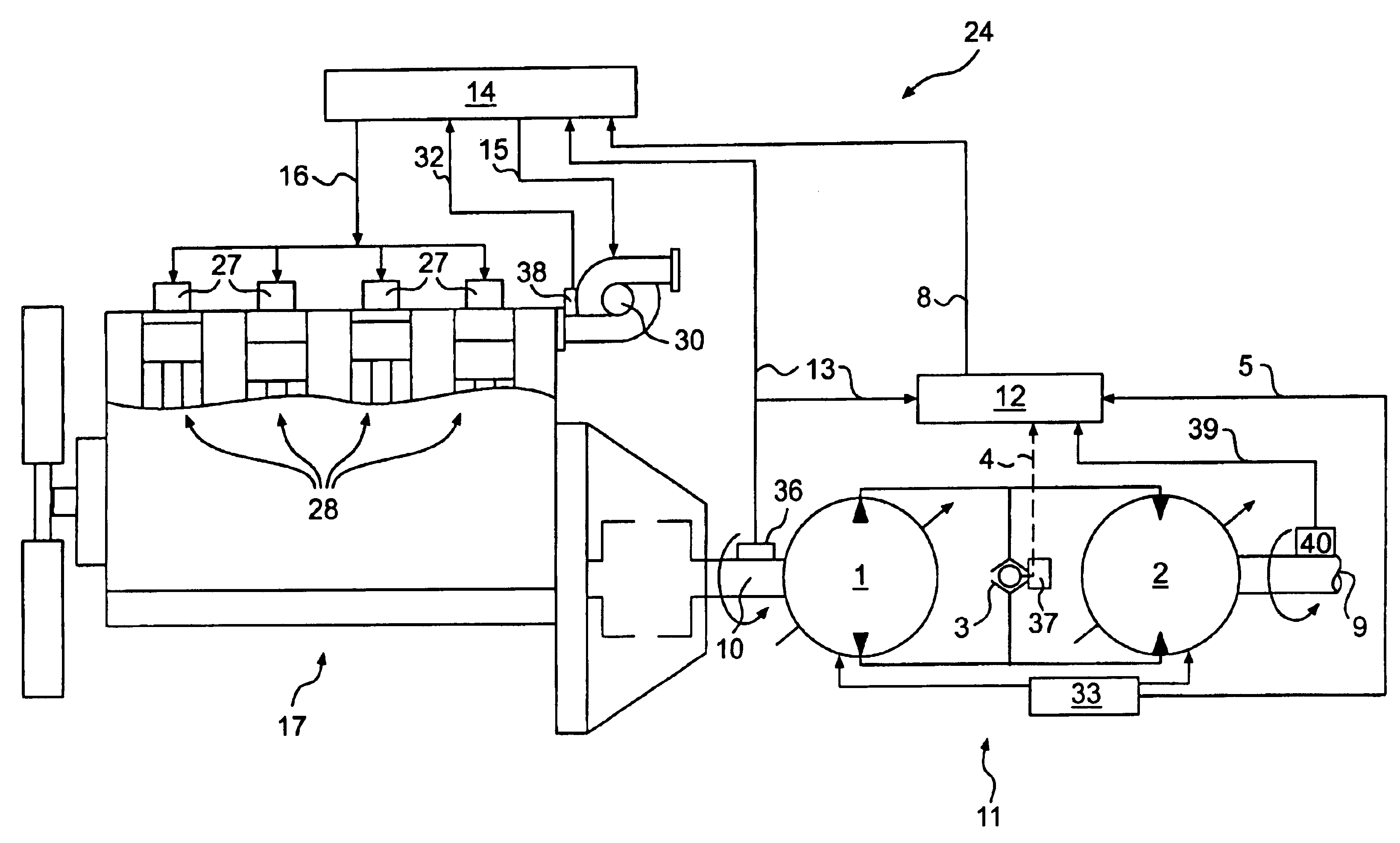
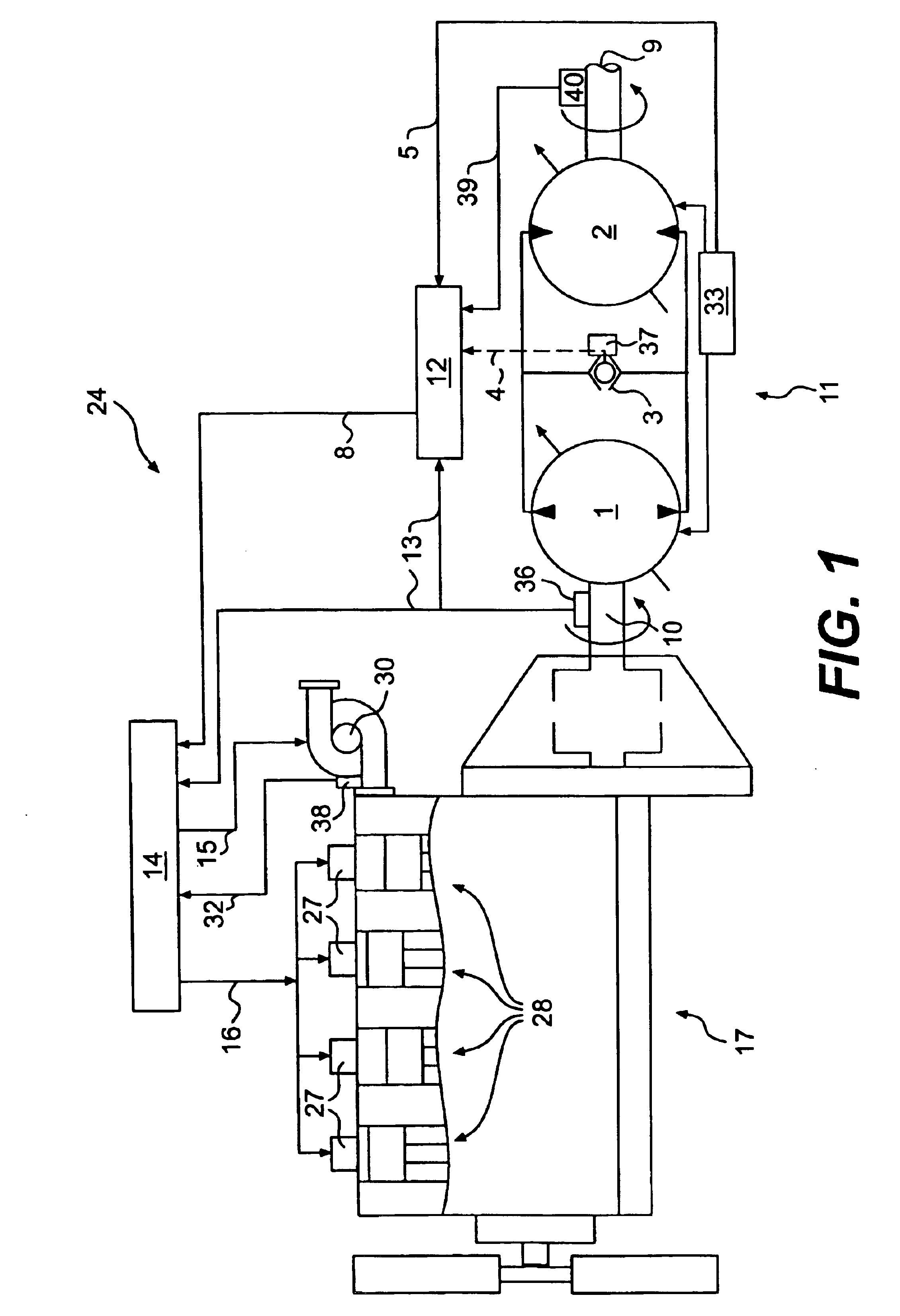
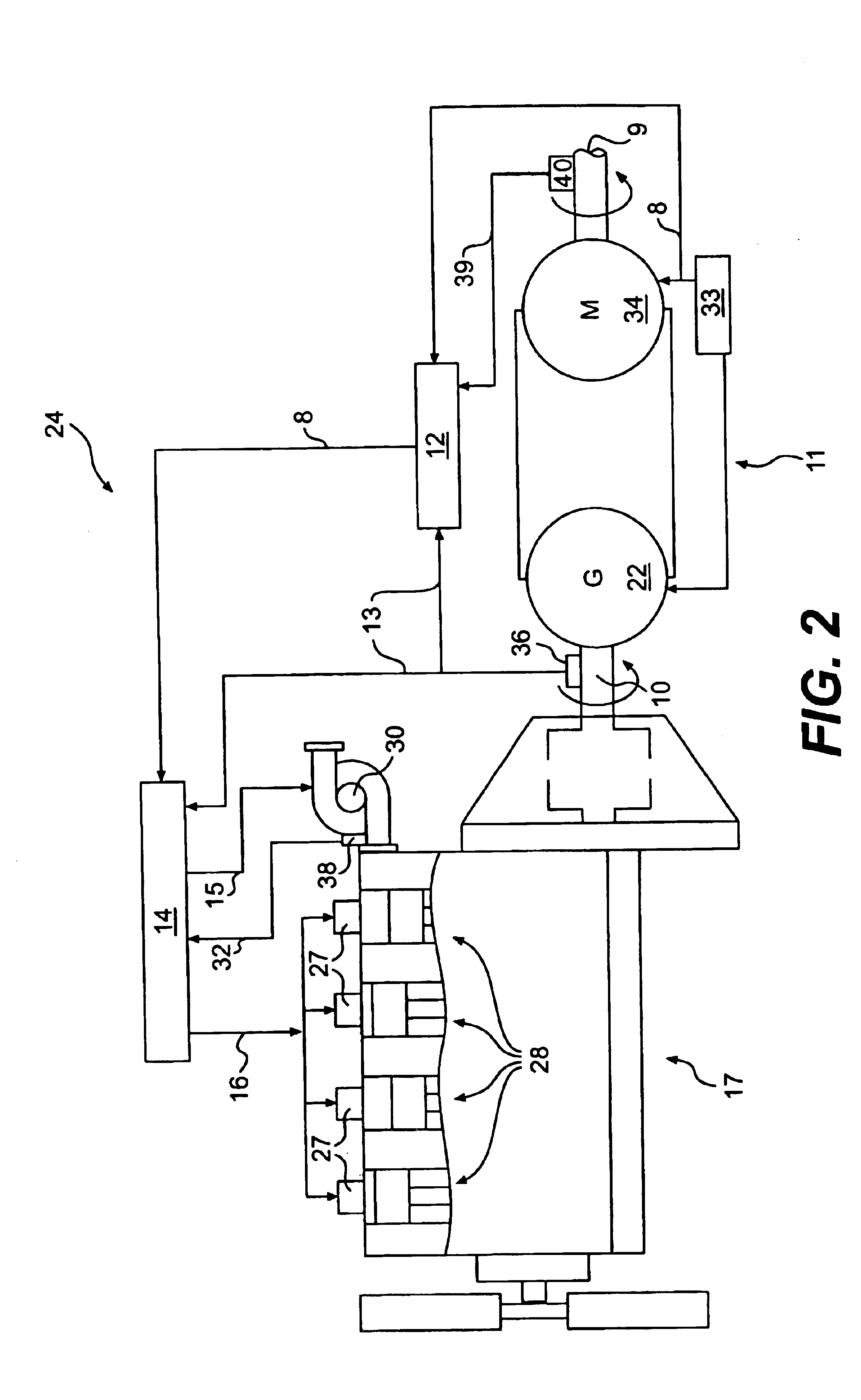
[0014]Exemplary embodiments of a predictive load management system are illustrated in FIGS. 1 and 2. The predictive load management system may be used, for example, with a power source 17 and a transmission 11. In the embodiments of FIGS. 1 and 2, the power source 17 is an engine, such as a turbo aspirated internal combustion engine. The engine may be a diesel engine, a gasoline engine, a natural gas engine, or any other engine readily apparent to one skilled in the art. The engine may also be naturally aspirated, supercharged, or have any other air induction system readily apparent to one skilled in the art. It is contemplated that the predictive load management system may be used with another type of power source such as, for example, a fuel cell.

[0015]As illustrated in FIG. 1, the power source 17 includes a plurality of combustion chambers 28. A fuel injector unit 27 is associated with each combustion chamber 28. In the illustrated embodiment, the power source 17 includes four co...


PUM


Abstract

A predictive load management system includes a power source operable to generate power output, the power source having a desired operating range. A transmission having a drive member is operably engaged with the power source. A control system is in communication with the power source and the transmission. The control system receives at least one input indicative of a load on the transmission and identifies a change in the load on the transmission based on the at least one input. The control system is further operable to determine a desired power output of the power source to account for the change in the load on the transmission. The control system modifies a performance characteristic of the power source to cause the power source to generate the desired power output when the change in the load on the transmission will result in the power source operating outside of the desired operating range.

Description

TECHNICAL FIELD[0001]This invention relates generally to a load management system and, more particularly, to a system and method for managing a predicted load on a power source.BACKGROUND[0002]Work machines such as, for example, wheel loaders, track type tractors, and other types of heavy machinery are used for a variety of tasks. These work machines include a power source, which may be, for example, an engine such as a diesel engine, a gasoline engine, or a natural gas engine, that provides the power required to complete these tasks. To efficiently perform these tasks, the work machines require a transmission that is capable of transmitting the torque generated by the engine over a wide range of speeds.[0003]Typically, work machines use a continuously variable transmission (CVT) to convert engine torque to drive traction devices, such as wheels or tracks that propel the work machine. Continuously variable transmissions are capable of providing a desired output torque at any speed w...

Claims


Application Information

Patent Timeline
Patent Type & Authority Patents(United States)
IPC IPC(8): E02F9/22F02D29/02F02D29/00F16H47/02F16H47/00F16H61/46F16H61/40F16H61/02G06F7/00G06F19/00B60W10/06B60W10/10B60W30/18F16H61/462F16H61/472
CPCB60W10/06B60W10/103B60W10/105B60W30/1882F16H61/462F16H61/472B60W2510/0623F16H2059/683B60Y2200/22F16H2059/148B60W2510/0671B60W50/0097
Inventor ROSE, CHARLES EARLKURAS, BRIAN D.VANDERHAM, MICHAEL EDWARDGUVEN, MUSTAFA KAMILSOPKO JR., THOMAS MICHAEL
Owner CATERPILLAR INC
Why Eureka
Try Eureka