Device and method for pressure control of cargo tank of liquefied natural gas carrier

a technology of liquefied natural gas and cargo tank, which is applied in the direction of liquid handling, container discharging methods, packaged goods types, etc., can solve the problems of difficulty in meeting the demand for cost reduction, and achieve the effect of smooth operation of the apparatus

Inactive Publication Date: 2005-06-07
MITSUBISHI SHIPBUILDING CO LTD +3
View PDF17 Cites 21 Cited by
  • Summary
  • Abstract
  • Description
  • Claims
  • Application Information

AI Technical Summary

Benefits of technology

[0019]In the method for controlling pressure in a cargo tank on a liquefied natural gas carrier in accordance with the present invention, BOG generated from liquefied natural gas stored in the cargo tank is supplied to a burning system through a compressor, and by using a second compressor disposed in parallel with a first compressor, connected with the burning system, on the downstream side of the cargo tank, a reliquefaction plant disposed on the downstream side of the second compressor and on the upstream side of the cargo tank, a mist separator disposed on the downstream side of the cargo tank, and a return pump provided between an inlet portion of the cargo tank and an outlet portion of the mist separator, the BOG passing through the mist separator and discharged from the s

Problems solved by technology

Therefore, the BOG is used merely as an auxiliary fuel for a boiler and

Method used


Image

  • Device and method for pressure control of cargo tank of liquefied natural gas carrier
  • Device and method for pressure control of cargo tank of liquefied natural gas carrier
  • Device and method for pressure control of cargo tank of liquefied natural gas carrier

Examples


first embodiment

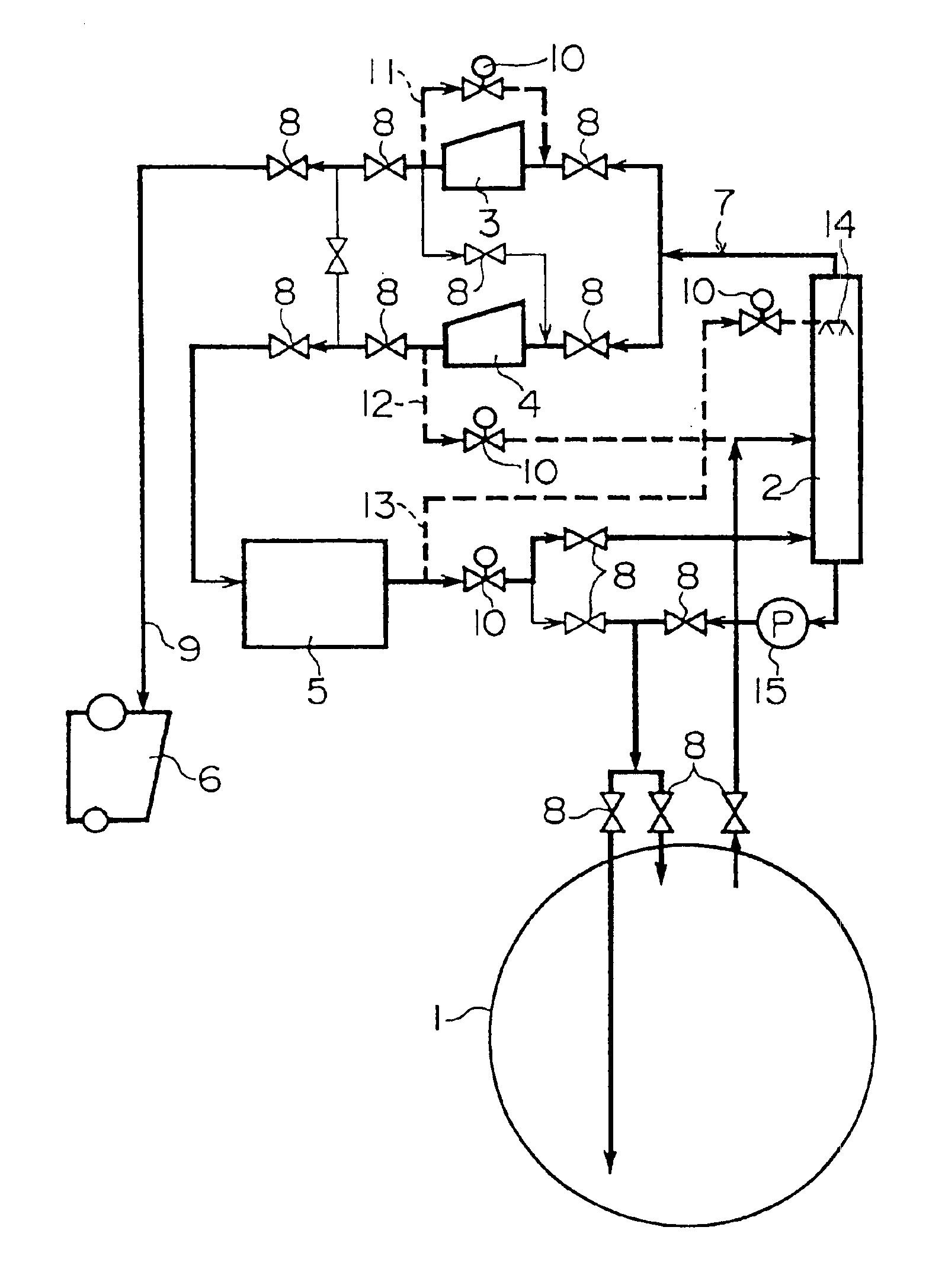
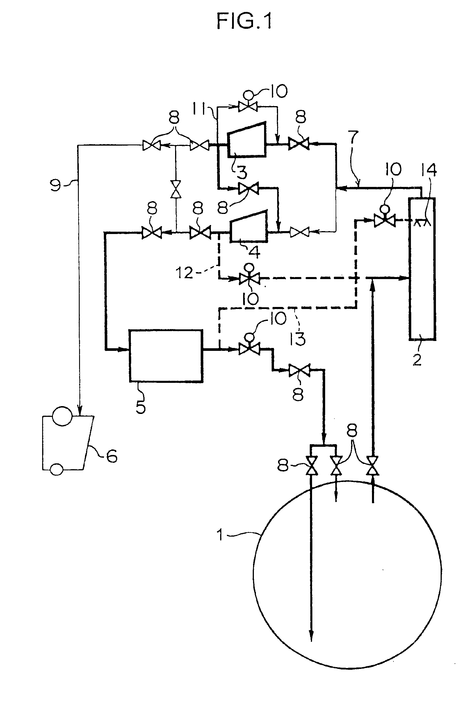
[0024]The present invention will now be described in detail with reference to embodiments shown in the accompanying drawings. FIG. 1 is a schematic view of a pressure control apparatus for a cargo tank on an LNG carrier in accordance with the present invention.

[0025]As shown in FIG. 1, the pressure control apparatus for a cargo tank on an LNG carrier in accordance with the first embodiment of the present invention includes a plurality of cargo tanks 1 for mainly storing LNG at a low-temperature (about −162° C.) under atmospheric pressure, one mist separator 2, first and second compressors 3 and 4, which are two BOG compressors, a reliquefaction plant 5, and a burning system (for example, a complete system for using BOG as boiler fuel) 6. Moreover, the cargo tank 1, the mist separator 2, the first compressor 3, the second compressor 4, and the reliquefaction plant 5 are connected to each other by a gas circulation main line 7 etc. to recover BOG (boil-off gas containing methane gas e...

second embodiment

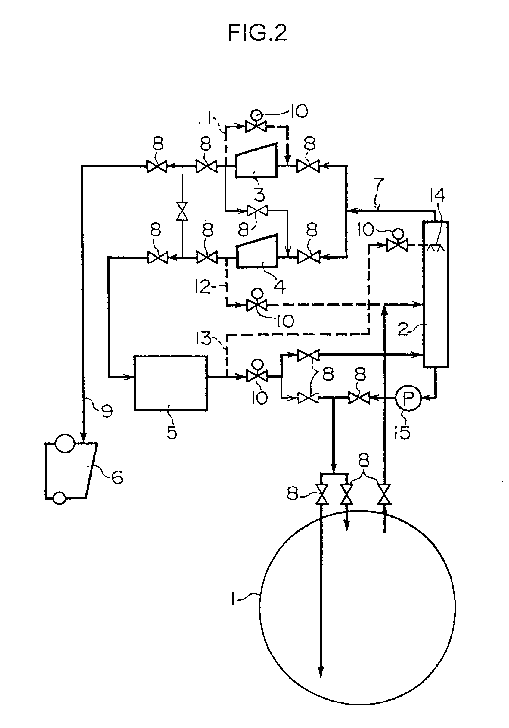
[0040]FIG. 2 is a schematic view of a pressure control apparatus for a cargo tank on an LNG carrier in accordance with the present invention.

[0041]The pressure control apparatus for a cargo tank on an LNG carrier in accordance with the second embodiment is different from the pressure control apparatus of the first embodiment in that the first compressor 3 and the second compressor 4 are disposed in parallel and that a return pump 15 is disposed between the inlet portion of the cargo tank 1 and a lower end outlet portion of the mist separator 2 as shown in FIG. 2. Specifically, the pressure control apparatus of the second embodiment is configured so that in the case where BOG exceeding the maximum capacity of the reliquefaction plant 5 is treated, the reliquefaction plant 5 and the burning system 6 can be operated in parallel. Also, the return pump 15 is provided to compress BOG so that the BOG can be returned into the cargo tank 1 smoothly because the pressure of BOG is low when the...


PUM


Abstract

An apparatus for controlling the pressure in a cargo tank 1 supplies BOG generated from liquefied natural gas stored in the cargo tank 1 to a burning system 6 through a compressor. In this apparatus, a reliquefaction plant 5 is disposed on the downstream side of first and second compressors 3 and 4 and on the upstream side of the cargo tank 1 so that BOG discharged from the second compressor 4 is liquefied by the reliquefaction plant 5 and the liquefied fluid is returned again into the cargo tank 1.

Description

TECHNICAL FIELD[0001]The present invention relates to an apparatus and a method for controlling pressure in a cargo tank on a liquefied natural gas (hereinafter referred to as LNG) carrier especially mounted with a reliquefaction plant.BACKGROUND ART[0002]In general, an LNG carrier is provided with a plurality of cargo tanks 51 as shown in FIG. 4. The cargo tank 51 stores low-temperature (about −162° C.) LNG, loaded at a loading site, at atmospheric pressure and carries it to an unloading site of destination. On this voyage, the pressure in the cargo tank 51 is increased by boil-off gas (hereinafter referred to as BOG) generated from the stored LNG.[0003]Therefore, on a conventional LNG carrier, in order to control the cargo tank pressure so as to be within a specified range to avoid the increase in pressure in the cargo tank 51, the cargo tank 51 is connected to a burning system (a complete system for using BOG as boiler fuel) 52 via regulating valves 53, a compressor 54, and the l...

Claims


Application Information

Patent Timeline
IPC IPC(8): F17C5/00F17C5/04F17C6/00F17C7/00F17C1/00B63B25/16F17C7/02F17C13/00F25J1/02
CPCF17C1/002F17C6/00F17C7/00F17C7/02F25J1/0025F25J1/0045F25J1/0208F25J1/023F25J1/0245F25J1/027F25J1/0294F17C5/04F17C2270/0105F17C2221/033F17C2223/0161F17C2227/0157F17C2265/03F25J2205/30F25J2220/64F25J2230/24F25J2230/60F25J2245/02F17C2223/033F17C2250/0626F17C2260/021F17C2265/032F17C2265/05F25J2230/30F25J2230/08F25J2210/04F25J2205/90F17C13/00
Inventor IRIE, TOSHIKAZUHATANAKA, NORIOMIHASHI, TAKASHITOMINAGA, EIJIOHTAKE, KAZUHIKOOKA, MASARUNAKAMURA, MORITAKAOMORI, MOTOHIRO
Owner MITSUBISHI SHIPBUILDING CO LTD
Why Eureka
Try Eureka