Support fixture

Inactive Publication Date: 2005-06-07
WFL MILLTURN TECH
View PDF6 Cites 2 Cited by
  • Summary
  • Abstract
  • Description
  • Claims
  • Application Information

AI Technical Summary

Benefits of technology

[0005]The task of the present invention is therefore to configure a support fixture of the aforementioned type in such a way that no deflection of the support elements occurs even when they are subjected to considerable loads and therefore to eliminate production inaccuracies. Indeed, it should be easily possible to block the adjustable components of the support fixture and thereby prevent unwanted adjustment movements. Furthermore, it is an intention of the present invention to make the support fixture small, to provide it with a wide adjustment range and to allow it to be operated outside the machine tool so that adjustments can be performed without difficulty and in a short period of time. The design by means of which this is to be achieved should be a straightforward one, although nevertheless permitting workpieces to be supported in a manner which permits safe and secure operation. Despite the ease of handling, therefore, a wide degree of flexibility should be assured.
[0011]Furthermore, it is advantageous for the threaded spindle to be located approximately in the center between the bearing pins of the support elements which form articulation points, to provide contact rollers for the workpiece on the support elements and to manufacture the housing using two plates kept at a distance from one another, with the support elements and their bearing pins inserted in between the plates. Furthermore, there should be a space provided in each of the support elements on both sides of the sliding blocks for accommodating the threaded spindle in the event of any misalignments.
[0012]Additionally, it is advantageous to provide the fixture with a support lever in a pivoting bearing in the housing and preferably actuated using a servo device, with the support lever acting on the side of the workpiece facing away from the support elements, and to equip the support elements with exchangeable adapters mounted on them.
[0013]If a support fixture is embodied in accordance with the present invention, then it is possible without any difficulty to adjust the two support elements by means of the threaded spindles connected to them by counter-rotating thread sections, with the threaded spindles at the side adjacent to the workpiece being actuated manually or by a machine and to block them once they have reached their operating position with the effect that the support elements are fixed in place and cannot be jolted out of position. In this case, the support elements are jointly moved towards or away from the center point of the workpiece which they are to support depending on the direction of rotation of the threaded spindles, with the result that an adjustment or readjustment can quickly and easily be performed after a workpiece has been inserted. Also, once the workpiece to be machined is lying on the support elements, the threaded spindles and the support elements connected to them are clamped against the housing in this operating position with the help of the locking device, meaning that any positional change of the workpiece and consequential production inaccuracies during its machining are practically excluded.
[0014]The construction complexity required to manufacture the support fixture is small, which means that it can be manufactured inexpensively. Also, because it is possible to select a large adjustment range for the swiveling support elements or due to the fact that they are equipped with an adapter and the proposed support fixture is small in size, the fixture can easily be used in a range of applications, in particular also on inclined bed machine tools.

Problems solved by technology

Although the support elements are adjusted jointly by the threaded spindle, it is not possible to provide satisfactory support for a workpiece while it is being machined.
Consequently, the application range for this support fixture of prior art is limited.

Method used


Image

  • Support fixture
  • Support fixture
  • Support fixture

Examples


Embodiment Construction

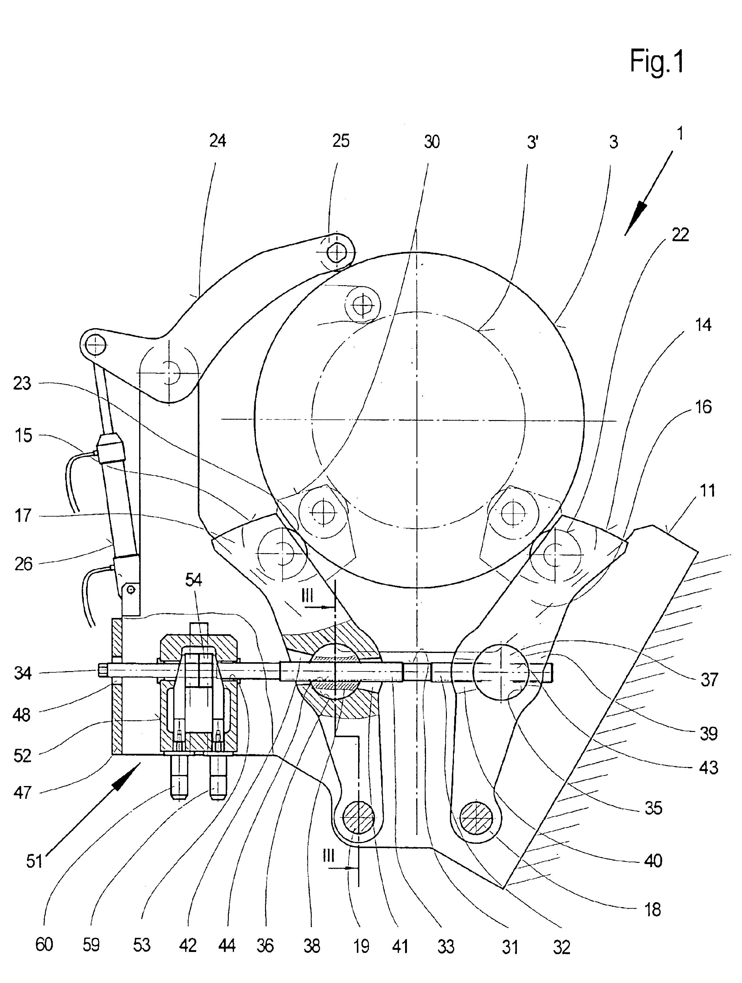
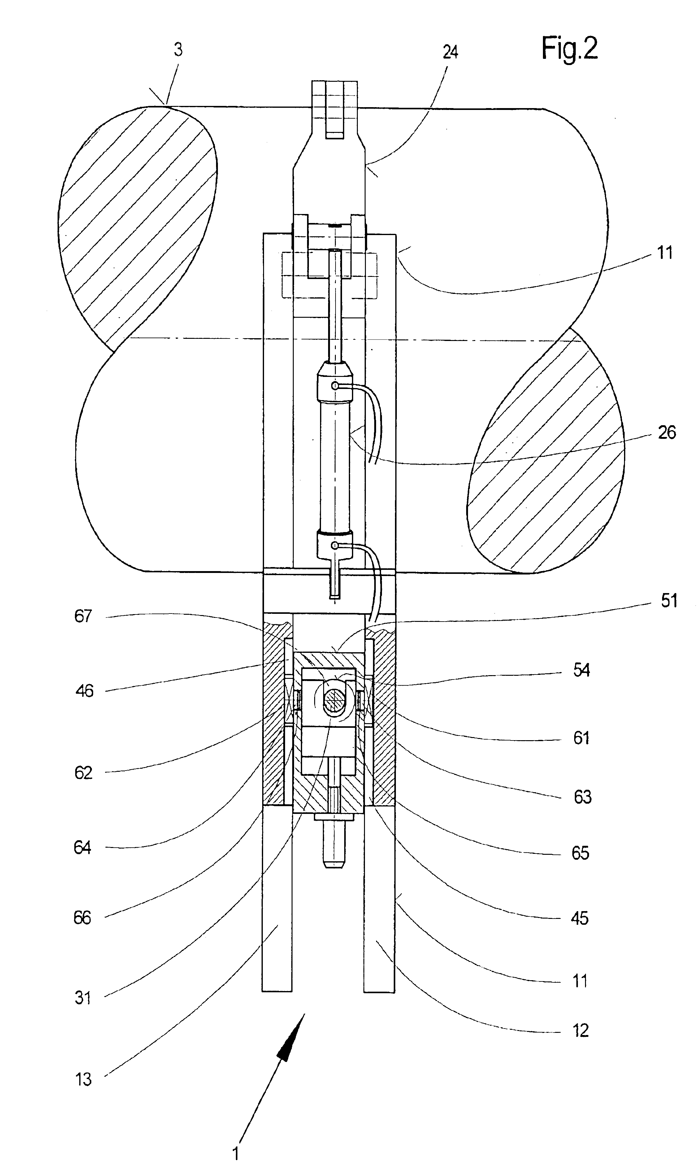
[0021]The fixture shown in FIGS. 1 and 2 and identified with 1 is used for supporting in particular large and heavy workpieces 3 in a machine tool 2, e.g. in an inclined bed turning and milling machine, and chiefly comprises two support elements 14 and 15 in a swiveling mounting in a housing 11, the support elements 14 and 15 being in a driven connection with one another for the purpose of joint adjustment by means of a threaded spindle 31. The threaded spindle 31 is provided with two counter-rotating thread sections 32 and 33 which engage in sliding blocks 37 and 38 held in the support elements 14 and 15, the sliding blocks 37 and 38 being provided with corresponding threaded holes 43 and 44.

[0022]In the sample embodiment illustrated, the housing 11 comprises two plates 12 and 13 arranged with a gap in between one another, in which, as shown in particular in FIG. 3, the ends of the support elements 14 and 15 formed as levers 16 and 17 facing away from the workpiece 3 are held in a ...


PUM

PropertyMeasurementUnit
Timeaaaaaaaaaa
Areaaaaaaaaaaa
Heightaaaaaaaaaa

Abstract

In a fixture for supporting a workpiece in a machine tool by means of two support elements held in a housing with the workpiece lying on them, the support elements are configured as levers held in a rotating mounting in the housing, the levers being driveably connected together by means of a threaded spindle. The threaded spindle has counter-rotating thread sections in areas corresponding to the support elements, and each of the counter-rotating thread sections of the spindle engage in a sliding block, the sliding blocks being rotatably mounted in holes in the support elements. The threaded spindle is provided with a device for locking the support elements in a set operating position. The two support elements are jointly adjustable and lockable, so that they can be set and readjusted within a short time and in a manner so that production inaccuracies are precluded.

Description

BACKGROUND OF THE INVENTION[0001]1. Field of the Invention[0002]The present invention concerns a fixture for supporting a workpiece in a machine tool, in particular a crankshaft in an inclined-bed turning and milling machine, by means of two support elements arranged at a lateral distance from one another and radially moveable in relation to the workpiece, the support elements being held in a housing, having the workpiece lying on them and with their ends facing away from the workpiece being formed as two levers in a swiveling mounting in the housing, in which case the levers are driveably connected to one another by a threaded spindle, with the threaded spindle displaying counter-rotating thread sections in its areas corresponding to the two support elements, with each of the threaded sections engaging in a sliding block and held in a rotating mounting in the holes worked into the support elements at an angle perpendicular to the threaded spindle.[0003]2. Description of the Prior A...

Claims


Application Information

Patent Timeline
IPC IPC(8): B23Q1/76B23Q1/00
CPCB23Q1/76Y10T82/2521Y10T82/2593Y10T82/2597
Inventor SIEGWART, RUDOLF
Owner WFL MILLTURN TECH
Why Eureka
Try Eureka