Pressurized liquid natural gas filling system and associated method

Active Publication Date: 2005-06-07
TW CRYOGENICS
View PDF6 Cites 15 Cited by
  • Summary
  • Abstract
  • Description
  • Claims
  • Application Information

AI Technical Summary

Benefits of technology

[0009]In a preferred embodiment, the liquid natural gas filling system is structured to deliver a small quantity of low pressure LNG to the vehicle fuel tank. This small quantity of low pressure LNG collapses the p

Problems solved by technology

Construction of such a v

Method used


Image

  • Pressurized liquid natural gas filling system and associated method
  • Pressurized liquid natural gas filling system and associated method
  • Pressurized liquid natural gas filling system and associated method

Examples


Example

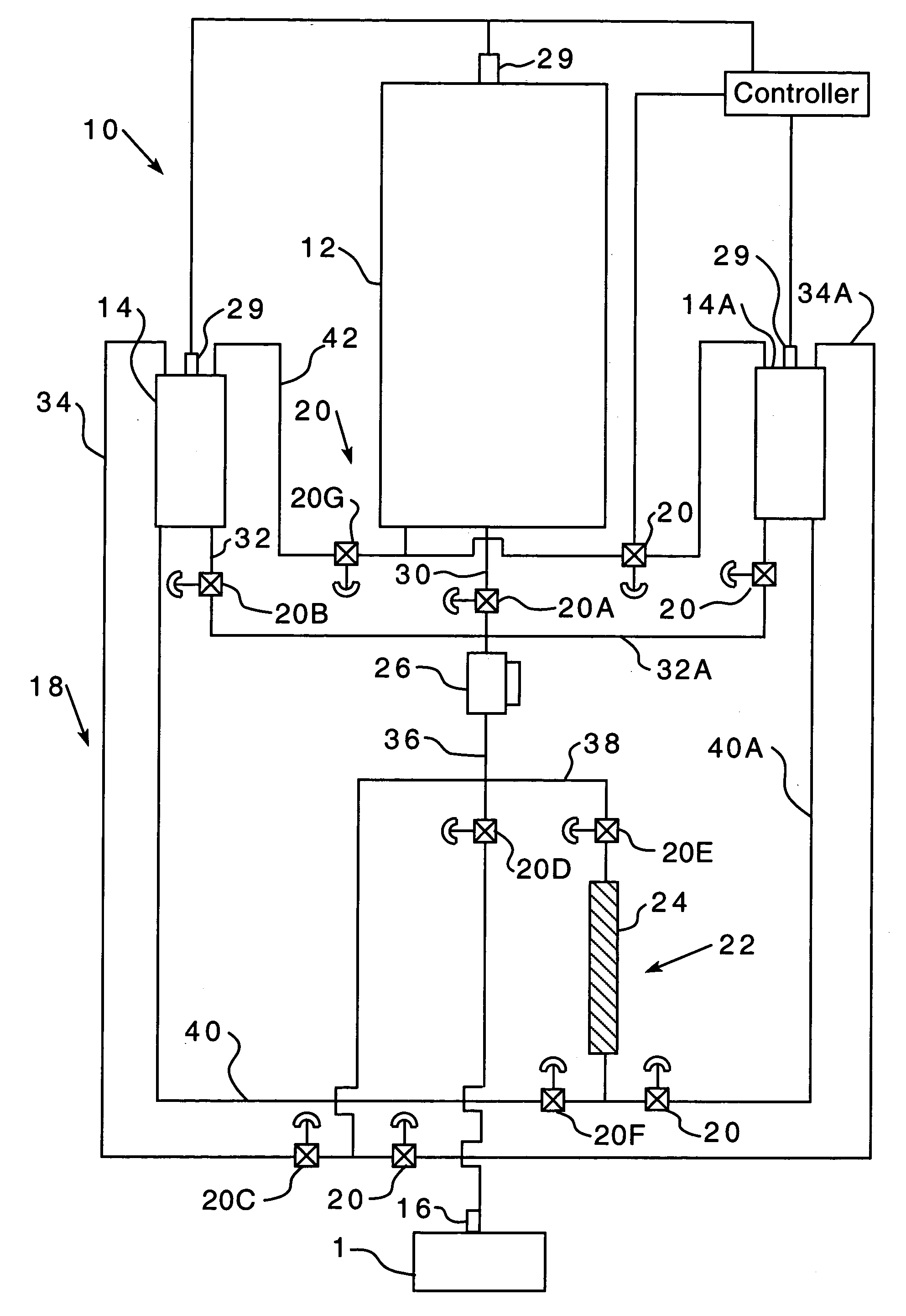
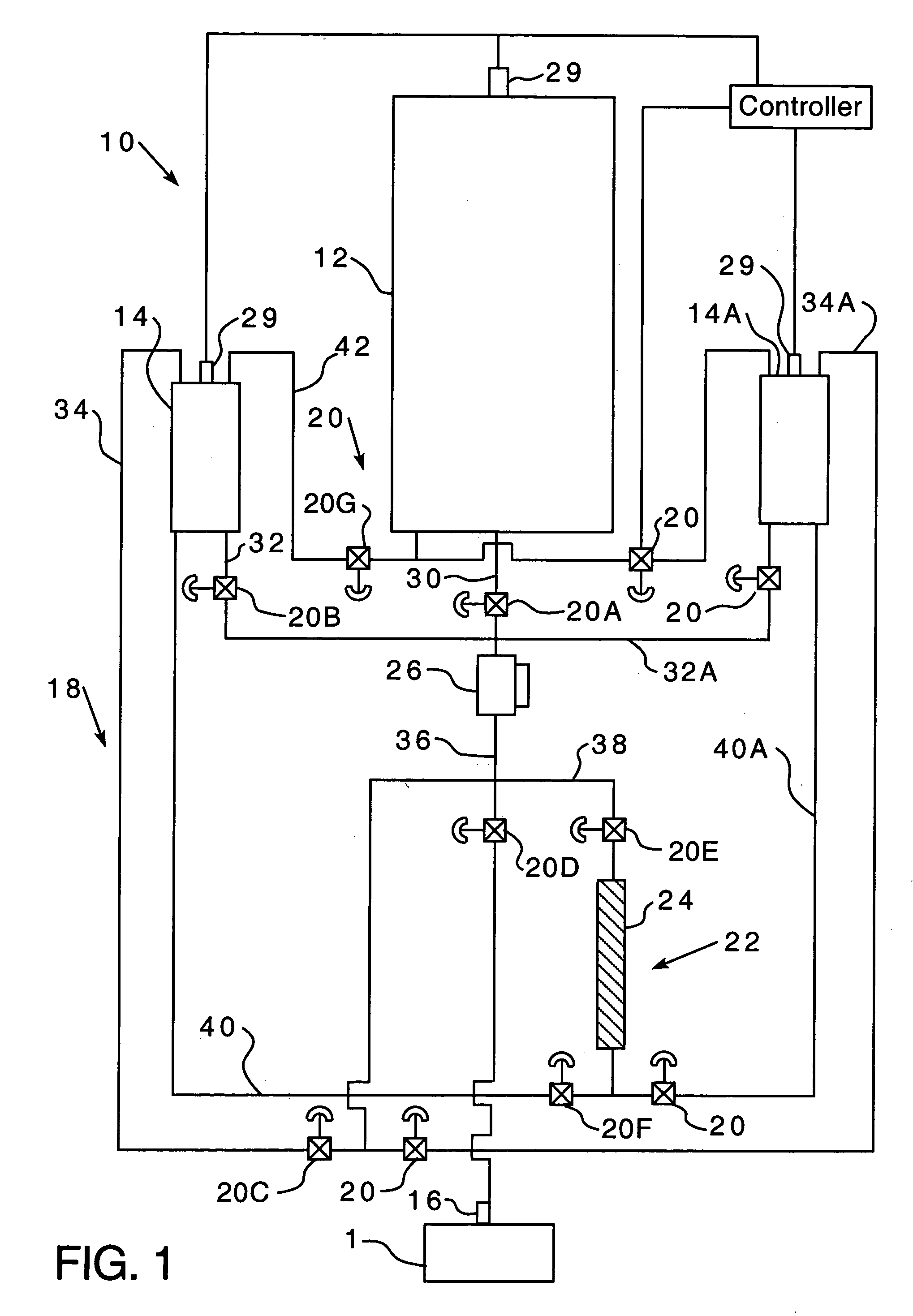
[0018]As shown in FIG. 1, a liquid natural gas filling system 10 includes a first, low pressure vessel 12, at least one second, high pressure vessel 14, a nozzle 16 structured to be coupled to a LNG vehicle fuel tank, a plurality of conduits 18 coupling, and providing fluid communication between, the first, low pressure vessel 12, the at least one second, high pressure vessel 14, and the nozzle 16. The first, low pressure vessel 12 is structured to hold a cryogenic liquid saturated at a pressure between about 10 and 100 psi, and more preferably at about 20 psi. The first, low pressure vessel 12 is also structured to hold a bulk quantity of cryogenic liquid, preferably between about 13,000 and 20,000 gallons of cryogenic liquid, and more preferably about 16,000 gallons of cryogenic liquid. The at least one second, high pressure vessel 14 is structured to hold a cryogenic liquid saturated at a pressure between about 90 and 125 psi, and more preferably at about 100 psi. The at least on...


PUM

PropertyMeasurementUnit
Timeaaaaaaaaaa
Pressureaaaaaaaaaa
Flow rateaaaaaaaaaa

Abstract

A liquid natural gas filling system structured to store a cryogenic fluid at a low pressure and fill a use vessel at a high pressure. The filling system includes a first, low pressure vessel, at least one second, high pressure vessel, a plurality of conduits, each conduit in the plurality having a valve, extending between, and in fluid communication within the first, low pressure vessel and the at least one second, high pressure vessel, a pressure building means coupled to the at least one second, high pressure vessel and structured to raise the pressure of a cryogenic liquid within the at least one second, high pressure vessel, and an outlet nozzle structured to be coupled to a use vessel, the outlet nozzle coupled via the plurality of conduits to, and in fluid communication with, the first, low pressure vessel and the second, high pressure vessel. The filling system is structured so that a cryogenic liquid may be stored in the first, low pressure vessel at a low pressure. The cryogenic liquid at a low pressure may further be transferred to the at least one second, high pressure vessel via the plurality of conduits. The pressure of the cryogenic liquid at a low pressure in the at least one second, high pressure vessel may be increased to a high pressure by actuating the pressure building means. Thus, the cryogenic liquid at a high pressure in the at least one second, high pressure vessel may be transferred from the at least one second, high pressure vessel to a use vessel via the plurality of conduits and the nozzle.

Description

BACKGROUND OF THE INVENTION[0001]1. Field of the Invention[0002]This invention relates to a liquid natural gas filling system and, more specifically, to a natural gas filling system having a low pressure vessel for holding a bulk quantity of liquid natural gas, and a high pressure vessel, for filling a use vessel, such as a fuel tank on a vehicle.[0003]2. Background Information[0004]There are an increased number of vehicles that use liquid natural gas (LNG) as a fuel. As such there is an increased need for filling systems to refuel the LNG vehicles and a need for such filling systems to hold an increased amount of fuel. It is understood that the pressure and temperature of a fluid in an enclosed space are related and that a higher pressure corresponds to higher temperature and a lower pressure corresponds to a lower temperature. Hereinafter, the pressure of the LNG will be identified as “high” or “low”, it is understood that LNG at a lower pressure is also at a lower temperature. Th...

Claims


Application Information

Patent Timeline
IPC IPC(8): B65B3/00B65B1/04B65B3/22B65B3/18F17C5/00
CPCF17C5/00F17C2270/0168F17C2221/033F17C2223/0161F17C2223/033F17C2227/0135F17C2227/0393F17C2227/04F17C2250/01F17C2250/032F17C2250/043F17C2250/0439F17C2250/0636F17C2265/065F17C2205/0326
Inventor HALL, IVAN KEITHGISH, JUSTIN CHARLES
Owner TW CRYOGENICS
Why Eureka
Try Eureka