Connector apparatus with seal protector and method of the same

a technology of sealing protector and connector, which is applied in the direction of valve details, valve arrangements, couplings, etc., can solve the problems of sealing member residing on the mating valve being displaced during activation or deactivation of the connector device, leakage and contamination of the fluid being conveyed, and sealing member peeling or buckled

Inactive Publication Date: 2005-06-07
COLDER PRODS
View PDF17 Cites 72 Cited by
  • Summary
  • Abstract
  • Description
  • Claims
  • Application Information

AI Technical Summary

Benefits of technology

[0006]In accordance with the present invention, improvements have been made upon existing designs for protecting sealing structures used for creating a seal between a valve and a coupler in various connector devices. Particularly, improvements have been made to provide a structure to protect sealing members in these connector devices, where a valve member having the sealing member can easily pass across a transverse outlet in a coupler member during opening and closing of the connector device.

Problems solved by technology

However, such devices where a mating valve passes an outlet transverse the direction of the inlet and transverse the direction of insertion of the mating valve, the sealing member residing on the mating valve can become displaced during activation or deactivation of the connector device.
As the mating valve continues to be inserted into the coupler to open the connector device, the sealing member may peel or buckle as it attempts to reengage and reseal with the sidewall of the coupler due to the interference of the extruded sealing member.
Such an event disrupts and compromises the sealing capability of the sealing member and can result in leakage and contamination of the fluids being conveyed.
While this solution may be possible, in applications requiring a sterile environment, such as in bioprocessing and fluid conveyance of the same, applying lubricants would not be desired or feasible for maintaining the seal when optimum sterile conditions are necessary.
However, such a structure for the outlet would likely need to be machined, as molding techniques do not yet support production of such an outlet.
Further, if the outlet was machined, such a device would be more costly for production using more expensive materials, rather than inexpensive moldable plastics, which are a desired material for such connector devices, particularly disposable connector devices.

Method used


Image

  • Connector apparatus with seal protector and method of the same
  • Connector apparatus with seal protector and method of the same
  • Connector apparatus with seal protector and method of the same

Examples


Embodiment Construction

[0037]In the following description of the illustrated embodiments, reference is made to the accompanying drawings that form a part hereof, and in which is shown by way of illustration of the embodiments in which the invention may be practiced. It is to be understood that other embodiments may be utilized as structural changes may be made without departing from the spirit and scope of the present invention.

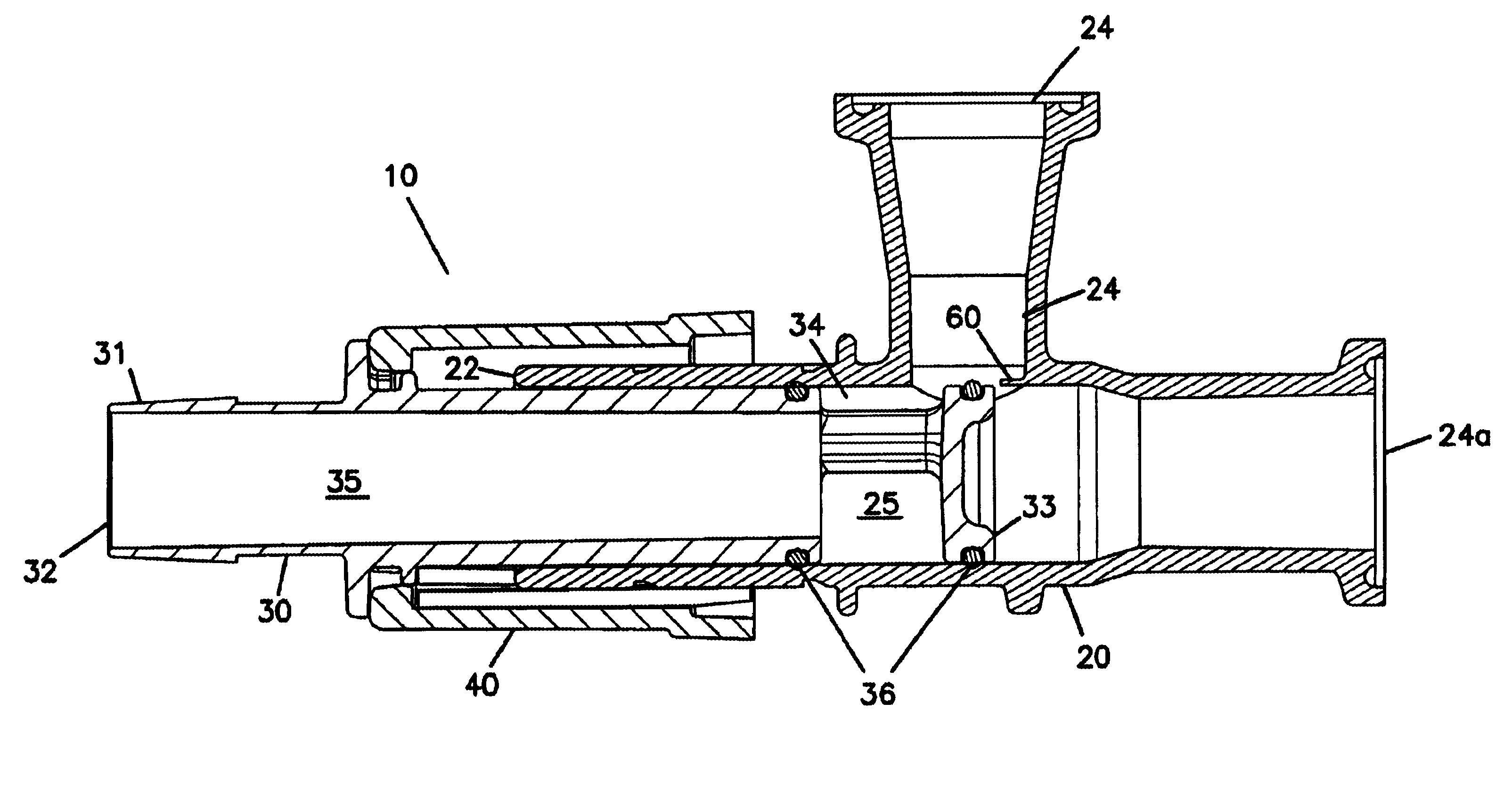
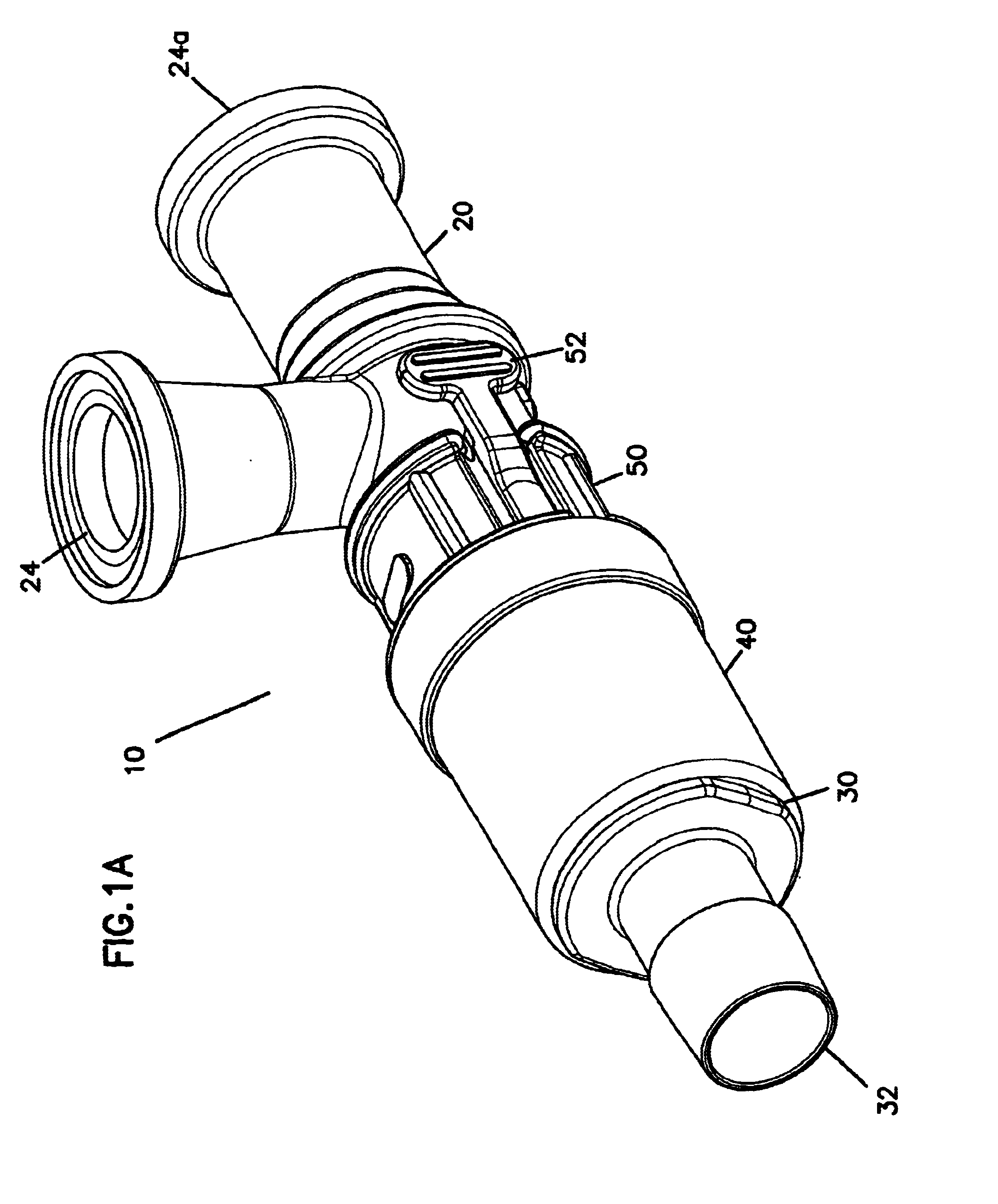
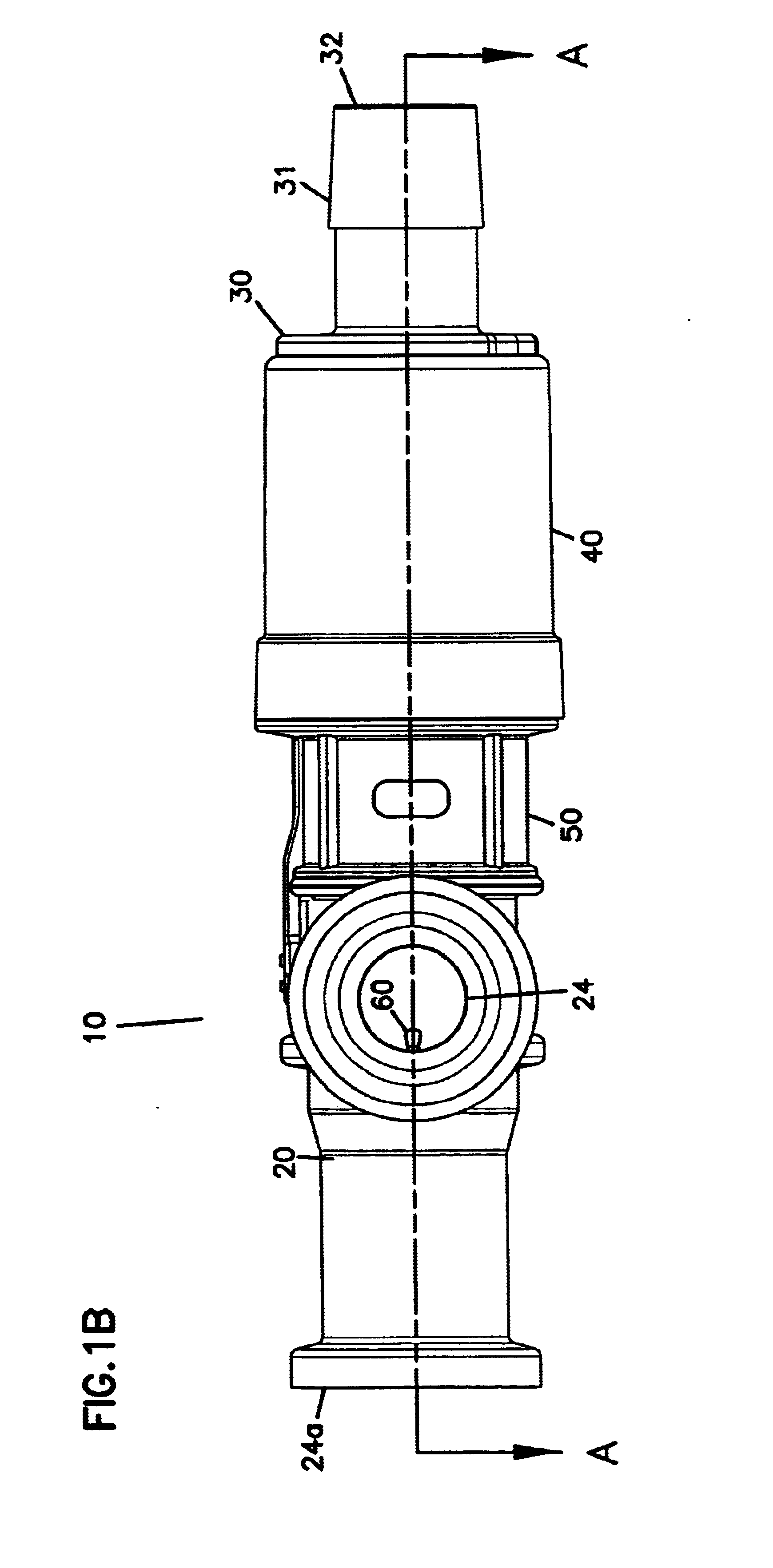
[0038]FIGS 1A-1C illustrate one exemplary embodiment of a connector apparatus 10 having a coupler 20 that is moveably connected with a mating valve member 30. Preferably, the coupler 20 and the mating valve member 30 are telescopically engaged and movable relative to one another. An adapter 40 may be connected with the valve member 30 to secure the valve member 30 to the coupler 20 when they are connected in both an open and a closed position of the connector apparatus 10. The coupler 20 and the valve member 30 also may be releasably connected. A stop member 50 is releasably attach...


PUM


Abstract

A connector apparatus having a coupler and a mating valve telescopically connected with the coupler. A planar member is disposed on the coupler within an outlet that is transverse to the inserting direction of the mating valve into the coupler. The planar member protects a sealing member that is disposed on the mating valve when the mating valve passes by the transverse outlet during opening or a closing of the connector apparatus.

Description

FIELD OF THE INVENTION[0001]This invention is generally related to a connector apparatus having a seal protector structure. More particularly, this invention is related to a connector apparatus having a coupler, and a mating valve telescopically connected with the coupler, where a sealing member disposed on the mating valve is protected by a planar member connected with the coupler when the mating valve passes by a transverse outlet.BACKGROUND OF THE INVENTION[0002]Connector devices employing a coupler and a telescoping mating valve are well known and widely used in many fluid conveyance and fluid dispensing applications. Typically, a coupler having an inlet and an outlet is connected with a mating valve that can be telescopically inserted into the coupler. The mating valve itself includes an inlet and an outlet, such that when the mating valve is inserted, the connector device can be actuated from a closed position to an open position where the outlets of both the coupler and the m...

Claims


Application Information

Patent Timeline
Patent Type & Authority Patents(United States)
IPC IPC(8): F16K3/26F16K3/00
CPCF16K3/262
Inventor DECLER, CHARLES PETER
Owner COLDER PRODS
Why Eureka
Try Eureka