Valve rod locking mechanism of valve

A valve stem and valve technology, which is used in the field of valves for natural gas transportation, can solve problems such as valve ball leakage, and achieve the effect of reducing pressure and preventing offset.

Active Publication Date: 2019-12-03
浙江伯替克阀门有限公司
View PDF4 Cites 0 Cited by
  • Summary
  • Abstract
  • Description
  • Claims
  • Application Information

AI Technical Summary

Problems solved by technology

[0005] In order to solve the problem that the existing valve used for natural gas transportation is easy to leak due to the floating of the valve ball during use, the present invention proposes a valve for natural gas transportation that can prevent leakage caused by the floating of the valve ball

Method used


Image

  • Valve rod locking mechanism of valve
  • Valve rod locking mechanism of valve
  • Valve rod locking mechanism of valve

Examples


Embodiment 1

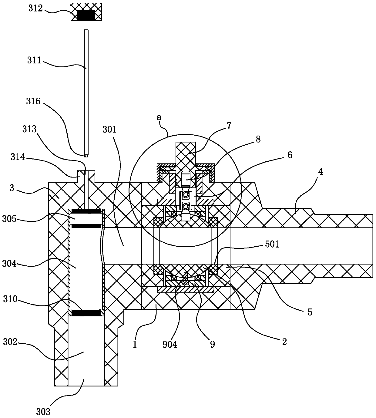
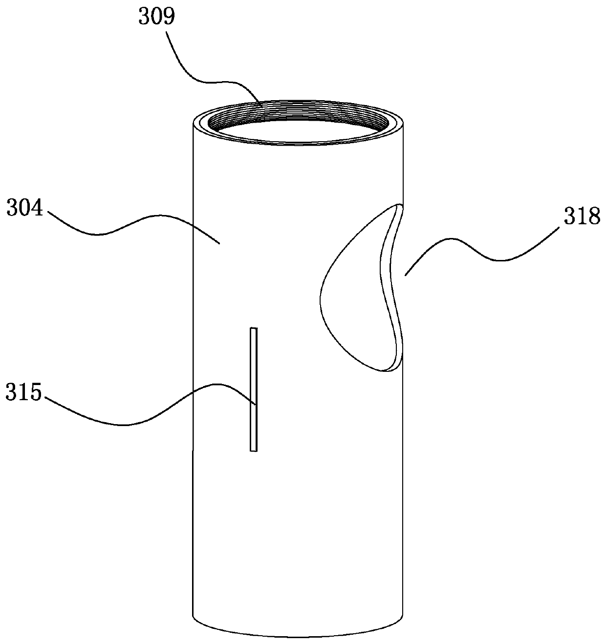
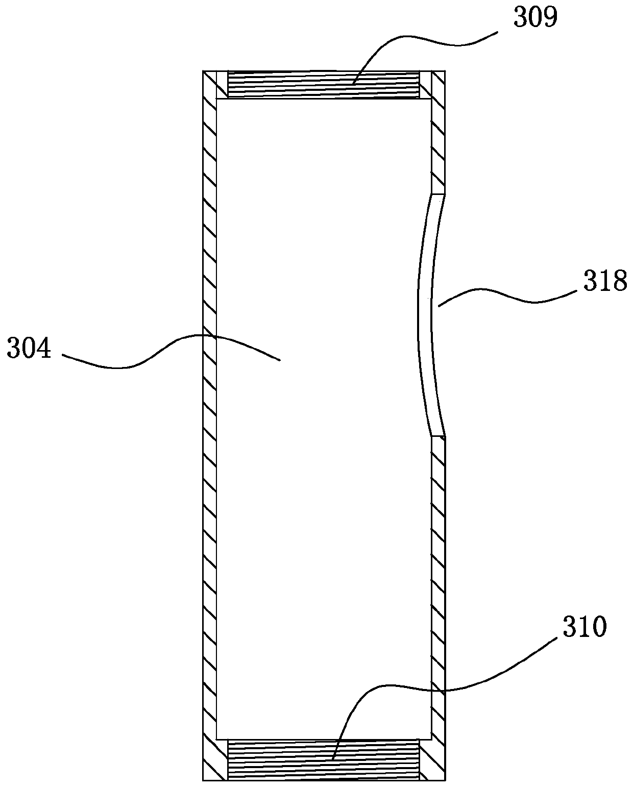
[0040] see Figure 1 to Figure 13 A valve for natural gas transportation described in this embodiment at least includes a valve seat 1, a valve ball 2 disposed in the valve seat 1, a valve stem 7 for driving the valve ball 2 to rotate, and a valve rod 7 disposed in the valve seat 1. The inlet connecting pipe 3 on one side and the outlet connecting pipe 4 on the other side of the valve seat 1, the two sides of the valve ball 2 are clamped and positioned by a positioning seat 5, and the two positioning seats 5 face the side of the valve ball 2 Both are provided with a first sealing ring 501 that fits with the outer wall of the valve ball 2. The upper side of the valve seat 1 penetrates through the inner and outer walls and is provided with a valve stem through hole 6, and the valve stem 7 is positioned in the valve stem through hole 6. The lumen of the air intake connecting pipe 3 includes a transverse channel 301 and a longitudinal channel 302, the upper end of the longitudinal...

Embodiment 2

[0053] see Figure 14 to Figure 17 , this embodiment further makes the following improvements on the basis of embodiment one:

[0054] It also includes a valve stem locking mechanism 12. The valve stem locking mechanism 12 includes a positioning sleeve 1201 and a lifting ring 1202. The positioning sleeve 1201 is coaxially embedded in the valve stem through hole 6. The The valve stem 7 realizes rotation and sealing cooperation with the valve stem through hole 6 through the positioning sleeve 1201, and several O-rings 705 are set on the valve stem 7, and the O-rings 705 are in rotation and sealing cooperation with the inner wall of the positioning sleeve 1201; The positioning sleeve 1201 is provided with several slideways 1203 and several air pressure passages 1204. The slideways 1203 correspond to the air pressure passages 1204 one by one. The slideways 1203 are arranged vertically. The opening at the lower end communicates with one end of the corresponding air pressure channe...

Embodiment 3

[0057] see Figure 18 to Figure 19 , this embodiment further makes the following improvements on the basis of embodiment one:

[0058] It also includes a valve stem sealing mechanism 13, the valve stem sealing mechanism 13 includes a positioning sleeve 1201 and an inflatable sealing ring 1301, the positioning sleeve 1201 is coaxially embedded in the valve stem through hole 6, the valve The rod 7 realizes rotational sealing cooperation with the valve stem through hole 6 through the positioning sleeve 1201, and several O-rings 705 are set on the valve rod 7, and the O-rings 705 are rotationally and sealingly matched with the inner wall of the positioning sleeve 1201; The inner wall ring of the positioning sleeve 1201 is provided with a sealing ring limiting groove 1302, and the inflatable sealing ring 1301 is set in the sealing ring limiting groove 1302 and the ring is set on the outside of the valve stem 7; the positioning sleeve 1201 is provided with an inflation channel 1303 ...


PUM


Abstract

The invention discloses a valve rod locking mechanism of a valve, and relates to the technical field of valves; the valve rod locking mechanism comprises a positioning sleeve and a lifting ring, the positioning sleeve is coaxially embedded in a valve rod through hole; the valve rod is in rotary sealing fit with the valve rod through hole via the positioning sleeve; a plurality of slideways and a plurality of air pressure channels are arranged in the positioning sleeve; the slideways are in one-to-one correspondence with the air pressure channels; a plurality of guide rods are arranged below the lifting ring; sliding blocks are arranged at the lower ends of the guide rods and correspond to the slidingways in a one-to-one mode, the guide rods are sleeved with compression springs used for resetting the lifting ring to the lowest position, a lower end face ratchet wheel with upward ratchets is arranged on the upper side of the lifting ring, and an upper end face ratchet wheel matched withthe lower end face ratchet wheel is arranged above the lower end face ratchet wheel and fixed to the valve rod. By arranging the valve rod locking mechanism, when natural gas leaks into the inner cavity of the valve rod through hole below the valve rod, the valve rod can be locked, people cannot rotate the valve rod any more, and then the possibility that the natural gas leaks from the valve rod is reduced.

Description

technical field [0001] The invention relates to the technical field of valves, in particular to a valve used for natural gas transportation. Background technique [0002] Valves used for natural gas transportation are generally ball valves. Compared with ball valves for water, ball valves for natural gas have higher requirements for sealing. If leakage occurs during use, it will cause greater harm. [0003] In the existing ball valve structure, the valve ball is floating. When the ball valve in use is in a closed state, the air pressure on one side of the valve ball will be greater than the air pressure on the other side, and the valve ball will deviate to the side with lower air pressure. , natural gas is easy to leak from the sealing ring on the side of the small air pressure, which requires the sealing structure at the valve stem to prevent natural gas leakage. [0004] At the same time, the valve stem is positioned on the valve seat and can only rotate in the positionin...

Claims


Application Information

Patent Timeline
Patent Type & Authority Applications(China)
IPC IPC(8): F16K5/06F16K5/08F16K35/00F16K39/06F16K41/02
CPCF16K5/061F16K5/0647F16K5/0689F16K5/0694F16K5/08F16K35/00F16K39/06
Inventor 宣琦
Owner 浙江伯替克阀门有限公司
Why Eureka
Try Eureka