Air flow passage for a vacuum cleaner

a vacuum cleaner and air flow passage technology, applied in the field of cyclone separation devices, can solve the problems of turbulent pressure loss, difficult to clear the blockage, increase the cost and complexity of the product manufacture, etc., and achieve the effect of reducing the back pressure, and improving the overall performance of the cyclone separation devi

Inactive Publication Date: 2005-06-07
OMACHRON INTPROP
View PDF110 Cites 119 Cited by
  • Summary
  • Abstract
  • Description
  • Claims
  • Application Information

AI Technical Summary

Benefits of technology

[0015]The configuration of the air intake conduit according to the present invention advantageously permits a substantial reduction in the back pressure caused by the air flow conduit which conveys the dirty air stream to the cyclone separation means. This reduction in pressure loss in the intake conduit may be used to improve the overall performance of the cyclone separation device. For example, a deeper vacuum may be drawn at the air intake of the cleaning head or other vacuuming device for a given vacuum motor size. Conversely, using the air flow path of the instant invention, the motor size may be reduced without a reduction in cleaning efficiency, thereby permitting a comparable vacuum cleaner to be provided at lesser cost.

Problems solved by technology

If the blockage occurs at a midpoint of the conduit, it may be difficult to clear the blockage.
Further, the addition of a port increases the cost and complexity of the manufacture of the product.
A bend in a conduit for a fluid causes a turbulent pressure loss in the conduit as the fluid travels through the bend in the conduit and the greater the sharpness of the bend, the greater the pressure loss.

Method used


Image

  • Air flow passage for a vacuum cleaner
  • Air flow passage for a vacuum cleaner
  • Air flow passage for a vacuum cleaner

Examples


Embodiment Construction

[0078]The following description of improvements in cyclone separators is described in their use with a vacuum cleaner and in particular an upright vacuum cleaner. It will be appreciated that the improvements in cyclonic separators described herein may be used with canister vacuum cleaners, central vacuum cleaners, back pack vacuum cleaners as well as cyclonic separation devices of any sort, including industrial dust collection systems and liquid / liquid, liquid / gas and gas / gas separation systems. For example, they may be used with single or multiple stage of filtration assemblies, and may even be utilized where nested serial cyclones are employed.

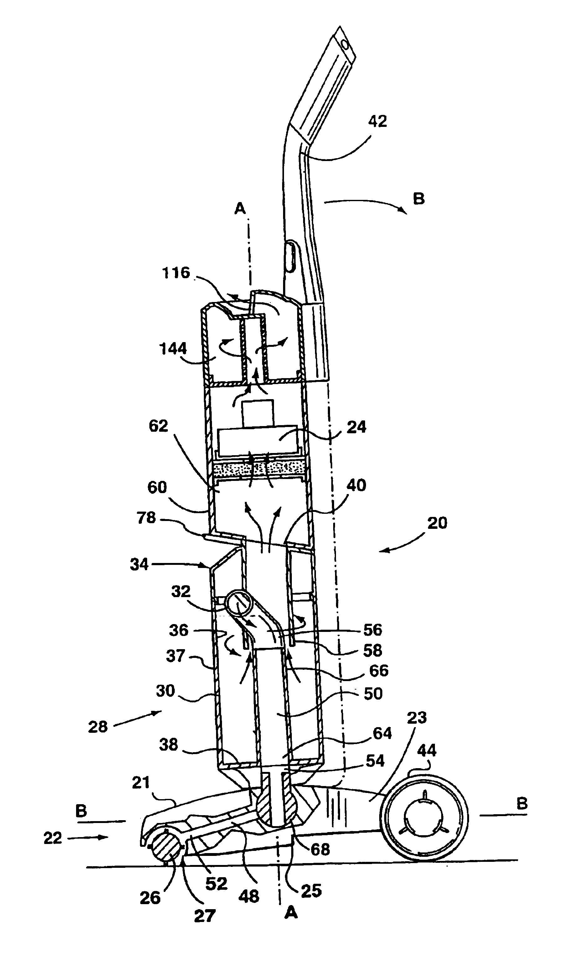
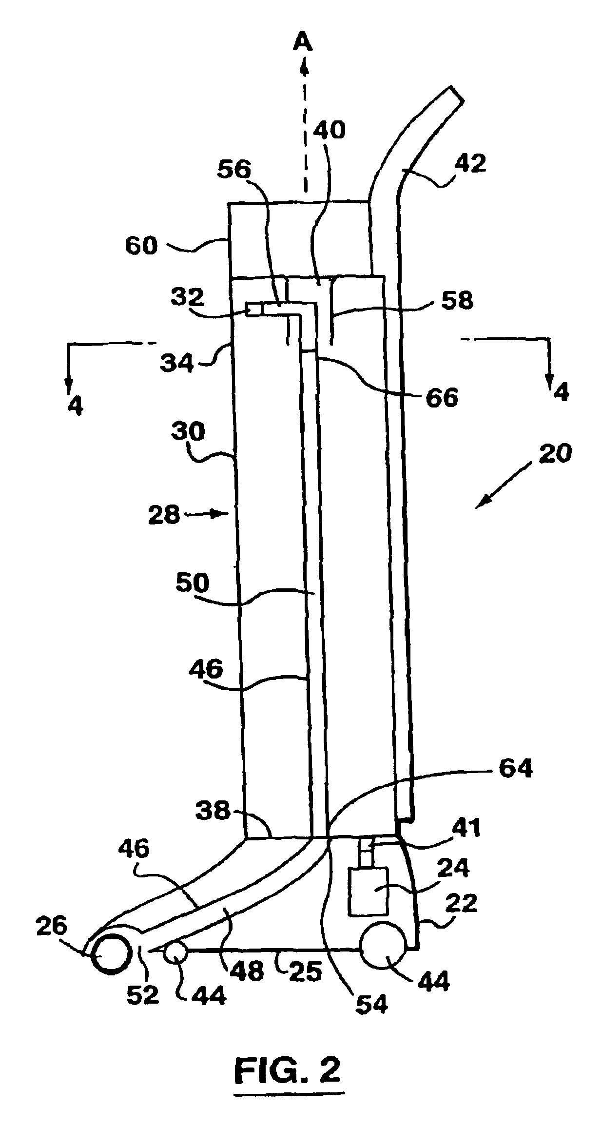
[0079]An upright cyclonic vacuum 20 according to the present invention is shown in the FIGS. 2, 3 and 3a. In the embodiment of FIG. 2, the motor is positioned in the cleaning head and the cleaned air is conveyed to the motor for cooling the motor. According to the embodiment of FIGS. 3 and 3a, the motor is positioned in the upper body portio...


PUM

PropertyMeasurementUnit
angleaaaaaaaaaa
anglesaaaaaaaaaa
angleaaaaaaaaaa

Abstract

A vacuum cleaner is provided having improved pressure loss characteristics. A fluid supply conduit in flow communication with an inlet to a cyclone is integrally formed as part of a cyclone bin. The present invention may be adapted for use with cyclonic separation devices of all types, including single- and multi-stage cyclonic separators.

Description

[0001]This application is a continuation of application Ser. No. 10 / 322,451, filed on Dec. 19, 2002 now U.S. Pat. No. 6,736,873 which is a continuation of application Ser. No. 10 / 188,412, filed on Jul. 8, 2002 now U.S. Pat. No. 6,599,340 which is a continuation-in-part of application Ser. No. 09 / 227,534, filed Jan. 8, 1999 and which has issued as U.S. Pat. No. 6,141,826, and is a divisional of application Ser. No. 09 / 480,168, filed on Jan. 10, 2000 and which has issued as U.S. Pat. No. 6,391,095.FIELD OF THE INVENTION[0002]The present invention relates generally to cyclonic separators. In one particular application, the invention relates to a vacuum cleaner which uses the cyclonic separation of dirt from an air flow as the primary dirt separation mechanism.BACKGROUND OF THE INVENTION[0003]The use of a cyclone, or multiple cyclones connected in parallel or series, has long been known to be advantageous in the separation of particulate matter from a fluid stream. Typically, a relative...

Claims


Application Information

Patent Timeline
Patent Type & Authority Patents(United States)
IPC IPC(8): A47L9/16A47L9/10B01D45/16B01D45/12B04C5/02B04C5/103B04C5/00A47L5/28A47L9/00
CPCA47L5/30A47L9/0009A47L9/1625A47L9/1641A47L9/165A47L9/1691B01D45/16B04C5/02B04C5/103A47L9/1666Y10S55/03
Inventor CONRAD, WAYNE ERNESTCONRAD, HELMUT GERHARDSZYLOWIEC, TED
Owner OMACHRON INTPROP
Why Eureka
Try Eureka