Welding wire feeder

a feeder and wire technology, applied in the direction of welding equipment, arc welding equipment, manufacturing tools, etc., can solve the problems of deteriorating welding quality, irregular loading of master wire feeding units, and small difference in the speed of wire feeding units

Inactive Publication Date: 2005-06-07
PANASONIC CORP
View PDF16 Cites 42 Cited by
  • Summary
  • Abstract
  • Description
  • Claims
  • Application Information

AI Technical Summary

Problems solved by technology

In practice, there may however be a small difference in the speeds between the wire feeding units.
The small difference is accumulated time to time and finally interrupt the welding.
However, when the wire feeding speed in the conventional wire feeders is periodically changed, e.g. is accelerated and decelerated for producing scale-like welding beads or at the start and end of the welding operation, the master wire feeding unit driven may be loaded irregularly due to a delay in an operation of the slave wire feeding unit.
This causes the wire feeding to be hardly consistent, thus making the welding quality deteriorate.
This cau...

Method used


Image

  • Welding wire feeder
  • Welding wire feeder
  • Welding wire feeder

Examples


Embodiment Construction

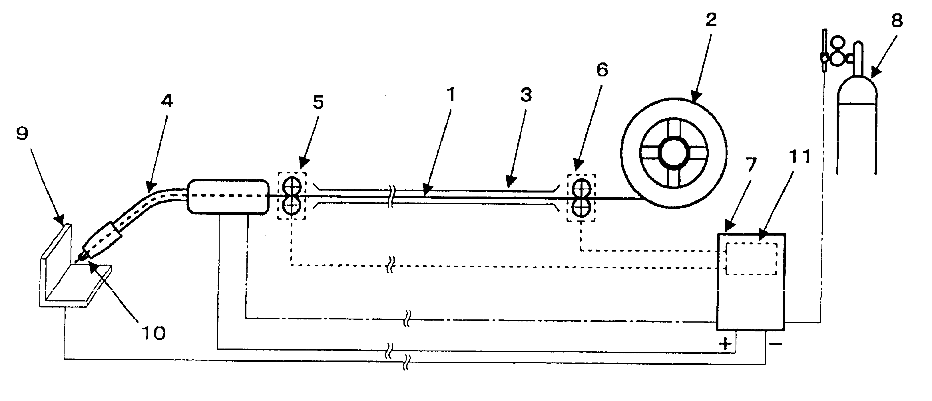
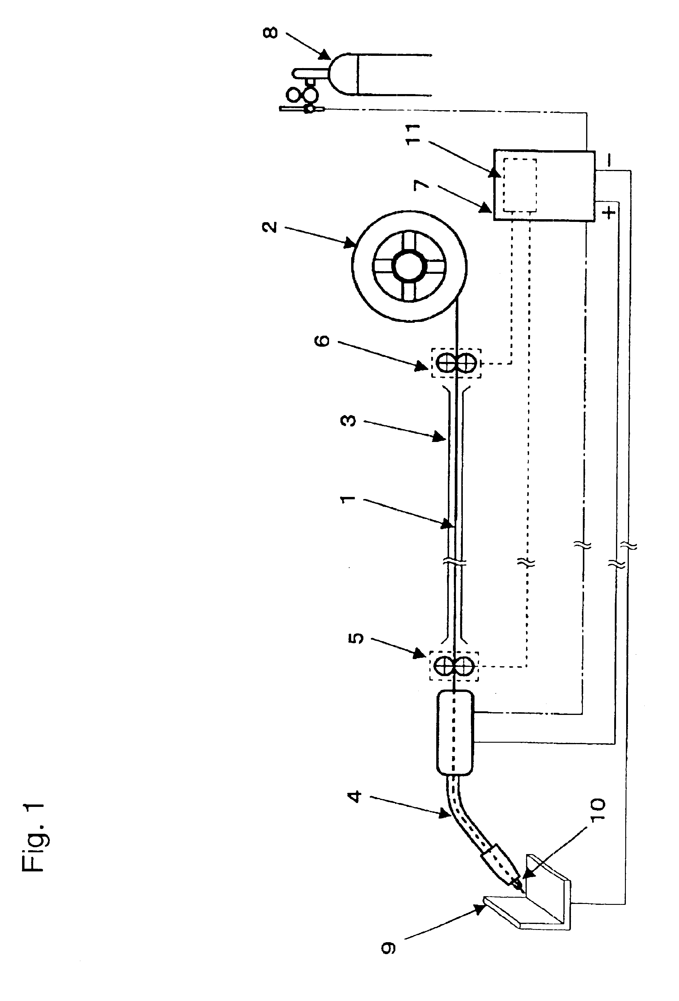
[0018]FIG. 1 is a schematic view of a welding wire feeder according to an exemplary embodiment of the present invention. A welding wire magazine 2 accommodates a roll of welding wire 1 wound. The welding wire feeder is disposed in a wire feeding passage extending from the welding wire magazine 2 via a wire guide tube 3 to a welding torch 4, and is a push-pull wire feeder including a pull-end feeding unit 5 located close to the welding torch 4 and a push-end feeding unit 6 located close to the welding wire magazine 2.

[0019]For shielding a welding point, shielding gas, i.e., inert gas contained in a gas container 8 is ejected from a top end of the welding torch 4 towards a workpiece 9 to be welded for shielding a portion to be welded. An arc welding source 7 applies a desired voltage between the welding wire 1, which is a consumed electrode, and the workpiece 9 at a contact tip 10 of the welding torch 4 to produce arc discharge between the welding wire 1 and the workpiece 9 for weldin...


PUM

PropertyMeasurementUnit
Diameteraaaaaaaaaa
Hysteresisaaaaaaaaaa

Abstract

A push-pull welding wire feeder includes plural wire feeding units provided in a wire feeding passage extending from a welding wire magazine, in which a roll of welding wire is accommodated, via a wire guide tube to a welding torch. At least one of the wire feeding units includes a torque limiter provided in a driving transmission system thereof for transmitting a driving force from a driving source to the welding wire. Accordingly, the welding wire feeder can steadily convey the welding wire even at acceleration or deceleration while allowing the welding wire to be bent, thus contributing to favorable result of its welding operation.

Description

[0001]THIS APPLICATION IS A U.S. NATIONAL PHASE APPLICATION OF PCT INTERNATIONAL APPLICATION PCT / JP02 / 07615.TECHNICAL FIELD[0002]The present invention relates to a welding wire feeder for feeding a welding wire to a welding torch.BACKGROUND ART[0003]In arc welding, it is necessary to stabilize a welding arc in order to maintain high quality of the welding. For the purpose, a welding wire has to be accurately fed to a welding station so that a length of the welding arc is constant.[0004]In case that arc welding employs aluminum which is too soft to be conveyed by a push feeder, or utilizes a long passage for feeding the wire, a push-pull welding wire feeder having plural wire feeding units is provided along the passage. The wire feeding unit generally includes a pair of rollers which hold the wire between them and are driven by a driving source, an electric motor.[0005]For steadily feeding the wire with the push-pull welding wire feeder, a pulling speed for pulling the wire at a pull...

Claims


Application Information

Patent Timeline
IPC IPC(8): B23K9/133B23K9/12
CPCB23K9/1336B23K9/133
Inventor MUKAI, YASUSHITAKAHASHI, WATARU
Owner PANASONIC CORP
Why Eureka
Try Eureka