Winding for electric rotating machine and manufacturing method for the same
a technology of electric rotating machines and windings, which is applied in the direction of windings, dynamo-electric components, and prefabricated windings. it can solve the problems of poor connection between the two, the decrease of the reliability of the welding, so as to achieve the effect of easy connection between the two and improve the quality of the connection
- Summary
- Abstract
- Description
- Claims
- Application Information
AI Technical Summary
Benefits of technology
Problems solved by technology
Method used
Image

Examples
first embodiment
[0023][First Embodiment]
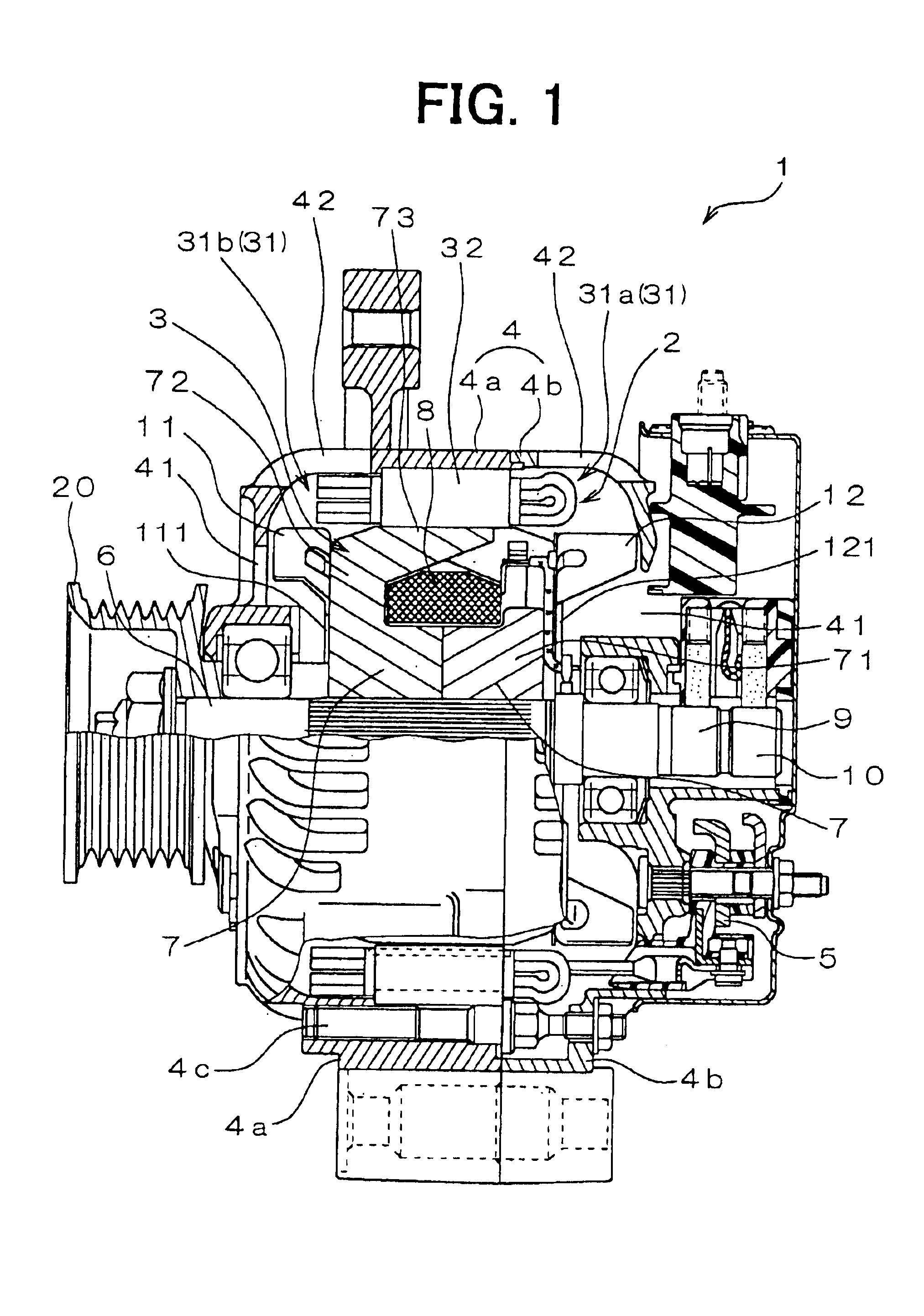
[0024]Referring to FIG. 1, a vehicular alternator 1 includes a stator 2, a rotor 3, a housing 4, and a rectifier 5. The rotor 3, which functions as a field magnet and rotates with a shaft 6, includes a Lundell-type pole core 7, a field coil 8, slip rings 9, 10, a mixed flow fan 11. The rectifier 5 is located away from a pulley 20. The shaft 6 is connected to the pulley 20 and driven by an engine (not shown) installed in a vehicle. The mixed flow fan 11 and a centrifugal fan 12 are air blowing devices.
[0025]The Lundell-type pole core 7 is constructed of a pair of pole cores. Each pole core includes a boss 71, a disc 72, and twelve claw poles 73. The boss 71 is assembled to the shaft 6. The disc 72 radially extends from the boss 71. The mixed flow fan 11 on a pulley side has two kinds of blades: one arranged at an acute angle and the other arranged at a right angle with respect to a base plate 111 fixed to an end face of the pole core 7. The centrifugal fan 12 ...
second embodiment
[0038][Second Embodiment]
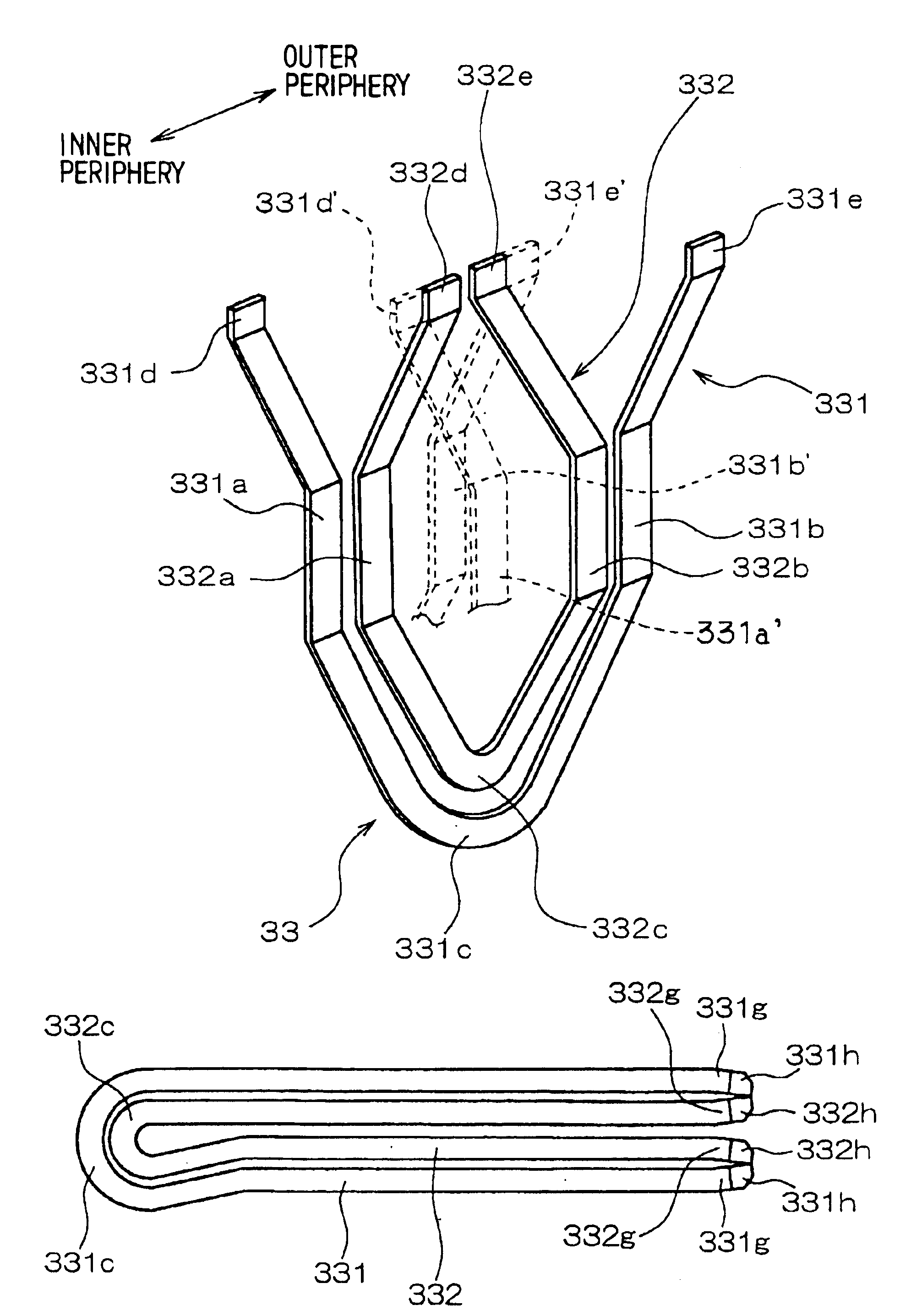
[0039]Referring to FIG. 7A, a press die is provided for altering shapes of the end portions 331g and 332g of the conductor segments 331 and 332. The press die includes a first die portion 100 and a second die portion 102. One surface of the first die portion 100 and the second die portion 102 are sloped, respectively. The first and the second die portions 100, 102 are set so that the end portion 331g is angled toward one side when the first and the second die portion 100, 102 are pressed against the end portion 331g.
[0040]A bare portion 331h is formed at the end of the end portion 331g. An insulating layer is removed from the bare portion 331h and a conductive member is exposed. The end portion 331g is bent by more than a distance corresponding to a thickness of the insulating layer 37 as shown in FIG. 7B, or a thickness of the removed insulating layer 37. The end portion 332g is altered in the same manner. The end portions 331g and 332g are angled toward e...
third embodiment
[0051][Third Embodiment]
[0052]Referring to FIG. 8A, the pressing die has an L-shaped first die portion 100a and a prism-shaped second die portion 102a. The end portion 331g is positioned between the first die portion 100a and the second die portion 102a. The first and the second die portions 100a, 102a are set so that the end portion 331g is angled toward one side when the first and the second die portion 100a, 102a are pressed against the end portion 331g.
[0053]The end portions 331g and 332g are angled toward each other by more than a distance corresponding to a thickness of the insulating layer 37 as shown in FIG. 8B. The end portion 332g is altered in the same manner. The end portions 331g and 332g are angled toward each other.
[0054]The present invention should not be limited to the embodiment previously discussed and shown in the figures, but may be implemented in various ways without departing from the spirit of the invention. For example, the winding can be applied to alterna...
PUM
 Abstract
Description
Claims
Application Information