Oscillating inductor

a technology of oscillating inductors and inductance, which is applied in the direction of inductance with magnetic cores, coils, electric variable regulation, etc., can solve the problems of high copper losses, high eddy current losses in copper windings, and high copper losses, so as to maximize the magnetic cross section, minimize the stray field, and reduce the effect of eddy current loss

Inactive Publication Date: 2005-06-07
VOGT ELECTRONICS AKTIENGES
View PDF2 Cites 48 Cited by
  • Summary
  • Abstract
  • Description
  • Claims
  • Application Information

AI Technical Summary

Benefits of technology

[0010]The invention is based on the object of providing an oscillating inductor which is physically as simple as possible and which allows greater miniaturization to be achieved than in the case of the oscillating inductors which are known from the prior art, without in the process having to accept significant adverse affects on the electrical, magnetic and thermal data.
[0011]In the case of the oscillating inductors according to the invention, the stray field is minimized owing to the maximization of the magnetic cross section. For each of the oscillating inductors according to the invention, this is a result of the particular absolute dimensions of the core in the oscillating inductor. Furthermore, the physical height is minimized by rotating the magnetic axis from the horizontal (prior art) to the vertical. The large magnetic surface areas result in optimum magnetic and electrical shielding in the direction of the external field. Furthermore, this results in a reduction in the eddy current losses into the surrounding, closely adjacent housing from electronic ballasts by positioning of the air gap in the center of the space. The large rear flaps on the cores in the oscillating inductors according to the invention provide each of the oscillating inductors according to the invention with good cooling capabilities, to be precise both in the direction of the board and in the direction of the housing.
[0012]Owing to the smoothness of the surfaces of the symmetrical double-E core in the oscillating inductor according to one aspect of the invention and of the E-I core in the oscillating inductor according to another aspect of the invention, the respectively corresponding oscillating inductor according to the invention can be picked up by suction or gripped automatically so that it is suitable for fully automated component-placement methods.
[0013]If the core is wound using a solid wire, there is no braid, which in turn overcomes the disadvantages described above with reference to braids. There is no need for the braid, owing to the minimal stray field in the air gap area and owing to the reduced number of turns resulting from the large effective magnetic cross section. In this embodiment, the higher filler factor resulting from the use of solid wires means that more copper can be introduced into the winding space than in the case of a braided winding. This results in a reduction in the resistive losses, which, overall, compensates for the majority of the undesirable frequency losses with solid wires, such as eddy current losses (which are relatively small owing to the small air gap and the small number of turns), skin effects and the proximity effect.

Problems solved by technology

Air gaps of this order of magnitude lead to high eddy current losses in the copper windings, caused by the stray field from the core.
The low AL value (permeability times the form factor) caused by the large air gap necessitates a relatively large number of turns, and this necessarily leads to high copper losses (Pv=I2·R).
These braided structures have a number of disadvantages in comparison to solid wires.
Their supply is more expensive, their temperature properties and their mechanical properties are not as good as those of normal varnished copper wires, braids are more difficult to wind than normal varnished copper wires and, finally, braids result in difficulties when fitting the wires to pins, owing to the unraveling effect.

Method used


Image

  • Oscillating inductor
  • Oscillating inductor
  • Oscillating inductor

Examples


Embodiment Construction

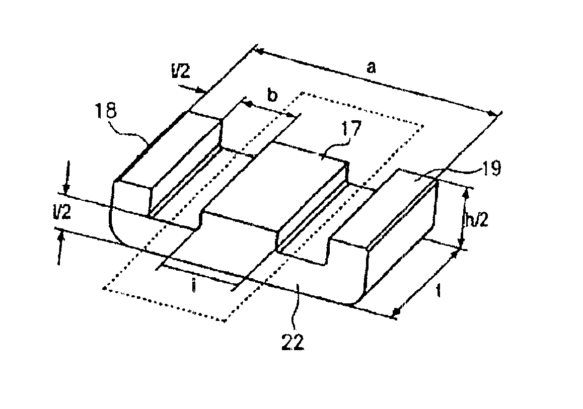
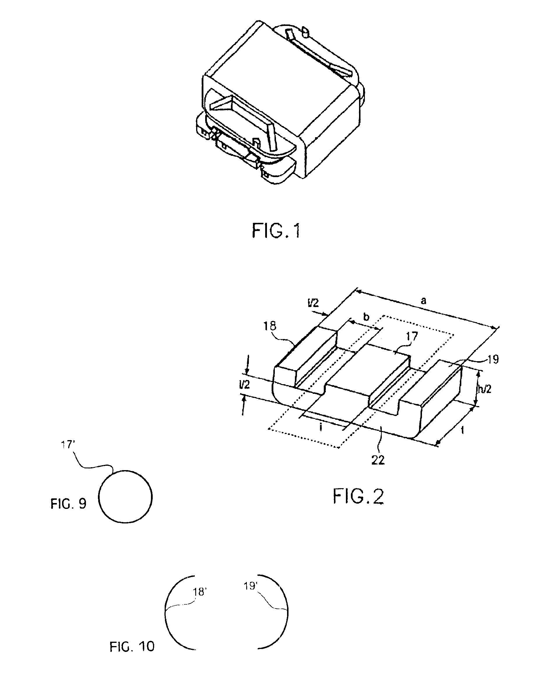
[0025]Quite fundamentally, the following explanatory notes should be preceded at this point by the following: even though the explanatory notes in the following text essentially relate to the description of the exemplary embodiments with a double-E core or with a double-EQ core, the explanatory notes also apply in an entirely corresponding manner to E-I cores and even, in a general manner, to core shapes with a center limb 17 and two outer limbs 18, 19. This is because the oscillating inductor properties that are required according to the object can also be achieved by such general core solutions. The only critical factors in each case are the criteria as defined in the individual independent patent claims.

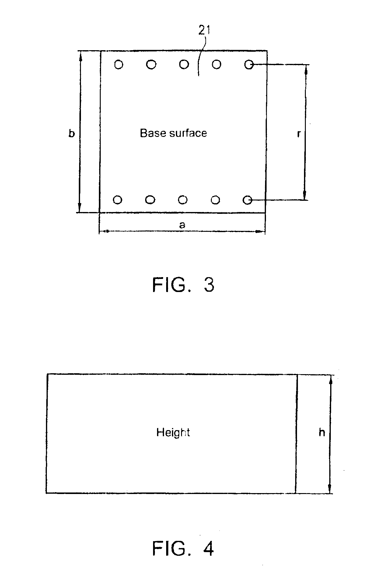
[0026]The basic configuration of oscillating inductors according to the invention with a symmetrical double-E core which has two geometrically identical core windows, a cuboid center limb 17 and two cuboid outer limbs 18, 19 is directly evident when FIGS. 1, 2, 5, 6 and 7 are cons...


PUM

PropertyMeasurementUnit
widthaaaaaaaaaa
widthaaaaaaaaaa
areaaaaaaaaaaa

Abstract

An oscillating inductor has a symmetrical double-E core, which has two geometrically identical core windows, a cuboid center limb and two cuboid outer limbs. The double-E core is designed such that a longitudinal cross sectional area of the center limb is greater than 90 mm2, with a longitudinal cross section being regarded as a cross section which would separate the double-E core into two single E-cores, and the cross section being at right angles to the longitudinal cross section such that the double-E can be identified in the cross section, with the double-E core being located in a component volume of less than 26.5 mm×26.5 mm×15 mm (width×depth×height).

Description

CROSS-REFERENCE TO RELATED APPLICATIONS[0001]This application is a continuation of International Application No. PCT / EP02 / 07760, filed Jul. 11, 2002.BACKGROUND OF THE INVENTION[0002]1. Field of the Invention[0003]The invention relates to oscillating inductors which are of wide distribution in electrical engineering.[0004]2. Description of the Background Art[0005]Nowadays, traditional standard kits from the E-core RM-range are preferably used in electronic ballasts for starting and operating fluorescent tubes, such as those described on pages 61-01 to 61-06 in the VOGT electronic AG “Inductive Component” catalogue from the year 2000.[0006]The increase in voltage in order to start fluorescent lamps is achieved by means of a series resonant circuit formed from an LC combination. This is described, for example, on pages 60-04 and 60-05 in the already mentioned VOGT electronic AG catalogue. In this case, voltages of up to 4 kVpp are produced across the coils, and currents of up to 3.5 A,...

Claims


Application Information

Patent Timeline
Patent Type & Authority Patents(United States)
IPC IPC(8): H01F41/02H01F5/02H01F17/04H01F27/29
CPCH01F5/02H01F41/02H01F17/04H01F27/292
Inventor BAUMANN, MICHAELWINKLER, JOHANN
Owner VOGT ELECTRONICS AKTIENGES
Why Eureka
Try Eureka