Camera and photographing lens barrel

a technology for photographing and camera, applied in the field of camera and photographing lens barrel, can solve the problems of increasing the diameter of the metal cylindrical member, difficult attachment, and design limitations, and achieve the effect of reducing design limitations

Inactive Publication Date: 2005-06-07
OLYMPUS CORP
View PDF5 Cites 6 Cited by
  • Summary
  • Abstract
  • Description
  • Claims
  • Application Information

AI Technical Summary

Benefits of technology

[0020]In order to solve the above-mentioned problems, it is one feature of the present invention to provide a camera which enables the reduction in limitations on appearance design of a portion for covering the periphery of a lens barrel portion therein and further enables a metal exterior portion.

Problems solved by technology

However, a barrel cover portion in the cover unit in the camera disclosed in Japanese Unexamined Patent Application Publication No. 7-20549 needs a taper for pulling out a mold and, when the length of the lens barrel unit is long, the base portion of the barrel cover portion in the cover unit is made thick, thereby causing the limitation on design.
Then, by adopting an exterior structure for inserting a metal cylindrical member into the barrel cover portion with the taper for pulling out the mold, a space is generated at the edge of the metal cylindrical member, the attachment is difficult, and the diameter of the metal cylindrical member is increased.
Although the barrel cover portion without the taper for pulling out the mold can be produced, unpreferably, the molding is complicated and a parting line is generated on the surface.
Further, upon attaching the metal cylindrical member, unpreferably on design, a fixed portion is exposed.
Furthermore, upon attaching no metal cylindrical member, the management of parts is complicated because the cover unit having a model name must be exchanged in association with the change in assembled camera model.
However, in this case, only the center is adjusted between holding frames for holding the lens groups but the optical center matching of the lens groups is not executed.
Therefore, the optical performance is not sufficiently obtained.
Further, the control operation is troublesome because the combination of the lens groups is not visually identified.
However, the conventional mounting structure of the printed-circuit boards 151a to 151f are not sufficient in views of a mounting area (planar area) for mounting an electric part and the small size of the arrangement space (space portion) 152a needs to be ensured and the large mounting area is further required.
In particular, the recent variation of camera specifications causes the addition of functions using an electronic device and, consequently, the camera has a pressing problem that the reduction in size of camera body is assured and the mounting area (planar area) of the printed-circuit boards can be increased.
The conventional electric devices have a problem that the increase in mounting area of the printed-circuit boards results in the growing in size thereof.
There is a danger that the cam follower drops off from the cam groove by applying unnecessary external force such as shock or fall in the assembling state in which the cam follower is slidably inserted in the cam groove of the frame member.

Method used


Image

  • Camera and photographing lens barrel
  • Camera and photographing lens barrel
  • Camera and photographing lens barrel

Examples


first embodiment

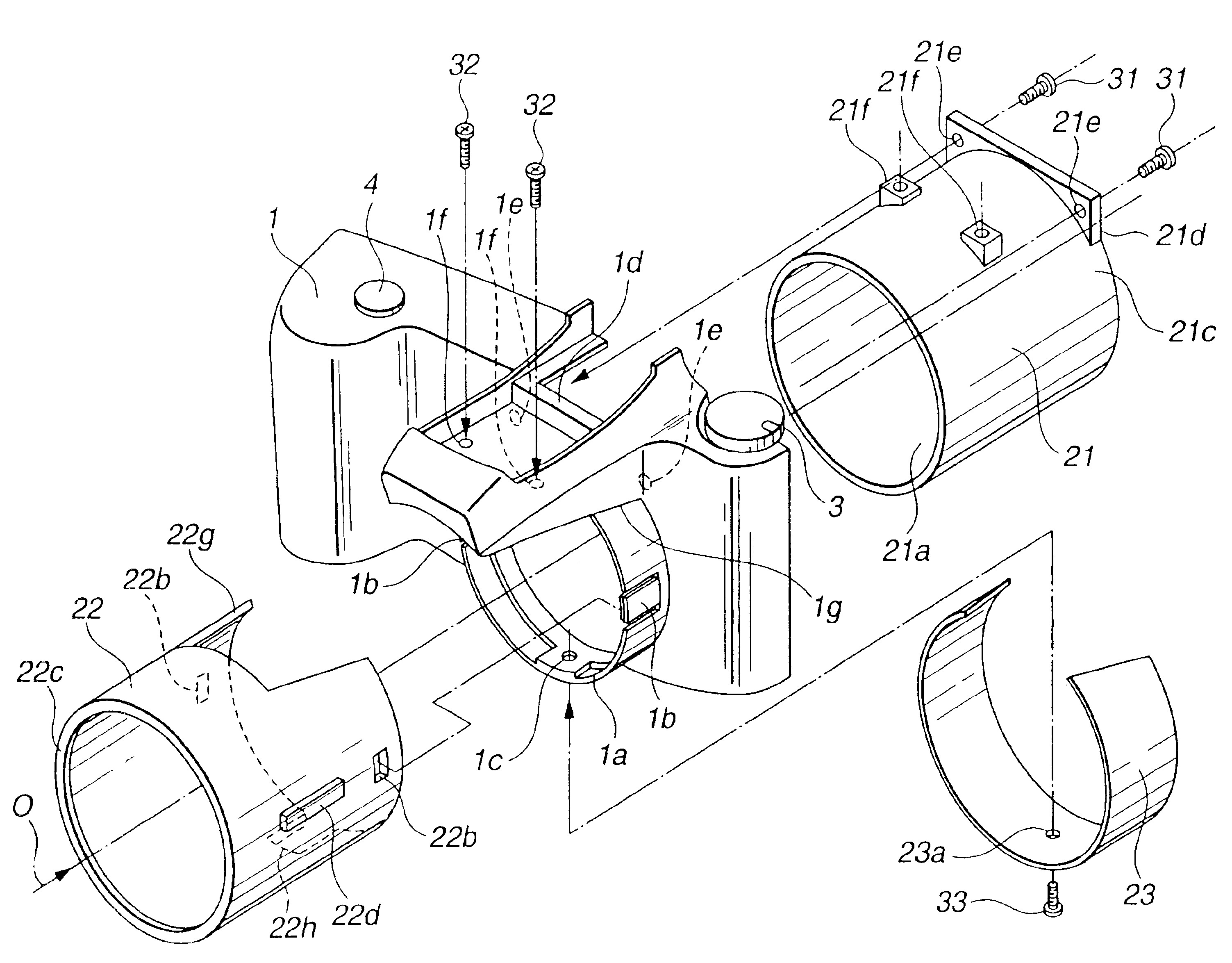
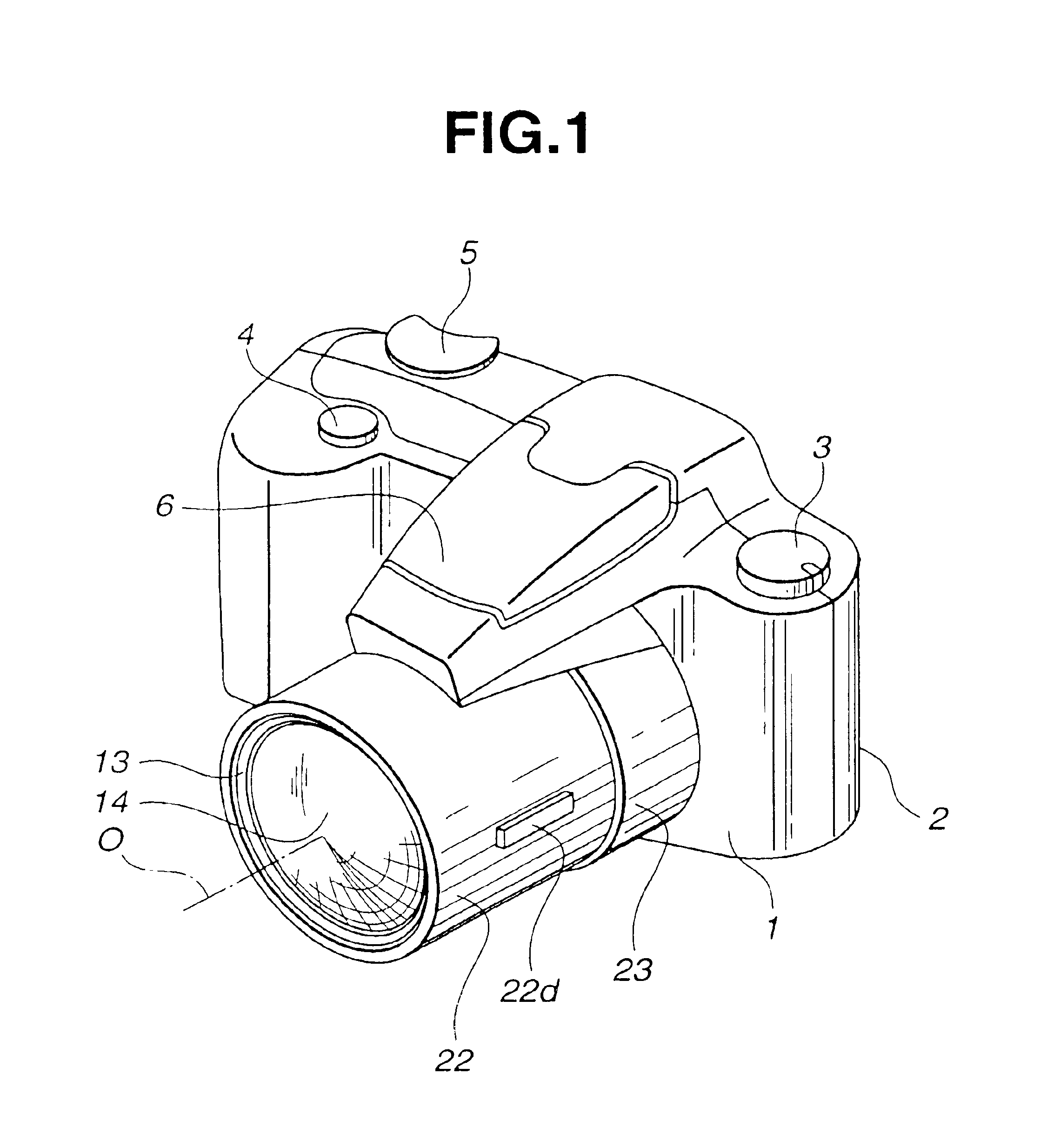
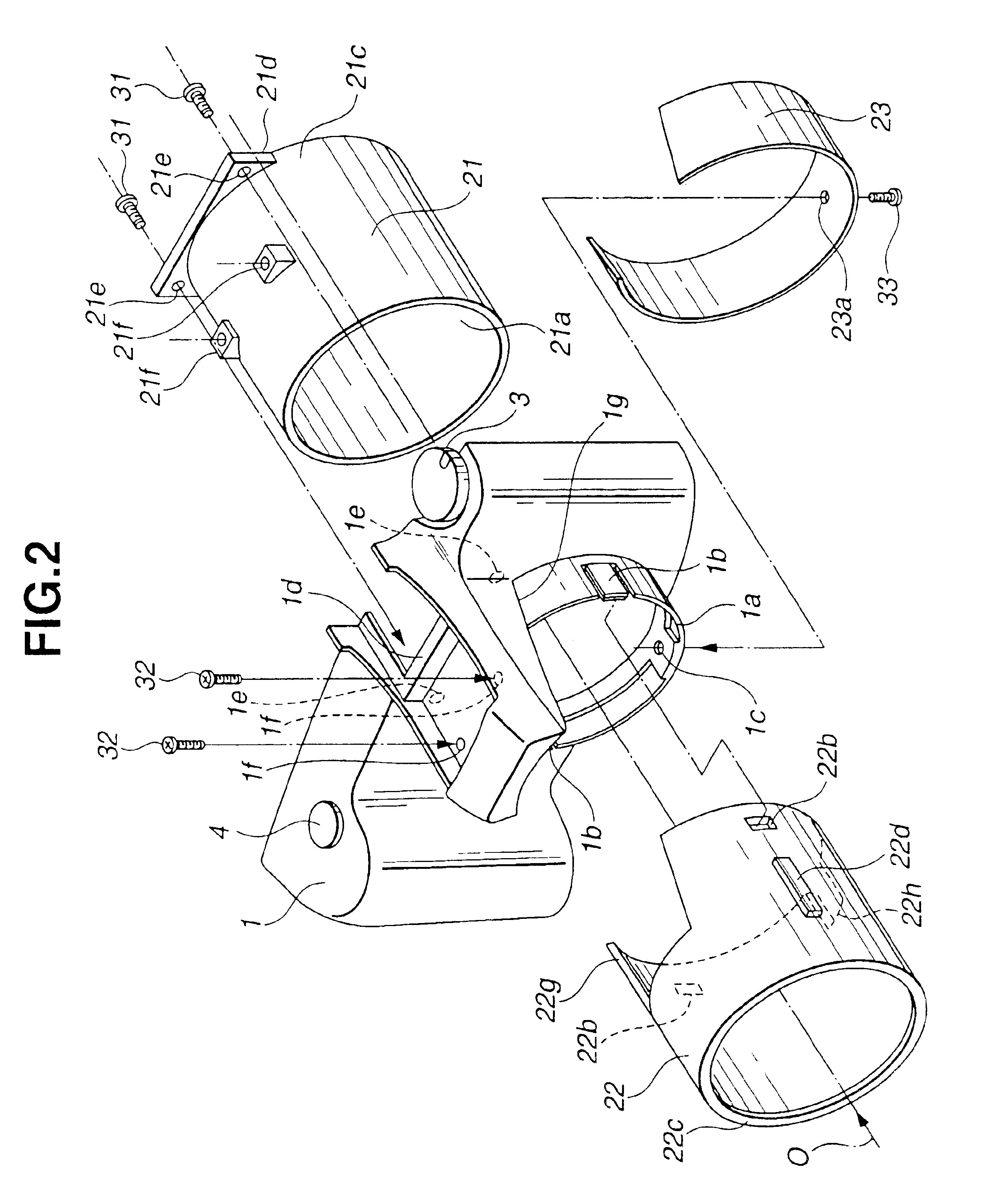
[0096]FIG. 1 is a an externally perspective view showing a camera according to the present invention. FIG. 2 is an exploded perspective view showing an exterior portion around a lens barrel unit of the camera. FIG. 3 is a longitudinal cross-sectional view around the lens barrel unit of the camera. FIG. 4 is a horizontally cross-sectional view around the lens barrel unit of the camera. In the following description, a subject side of the camera is in front and an image forming side is in the back.

[0097]Referring to FIG. 1, an exterior portion of the camera according to the first embodiment comprises: a front cover 1 and a rear cover 2, as members for covering a camera main body unit 11 (refer to FIG. 3) and as second members (second cylindrical members); an exterior cylindrical member 22 made of metal as a third member (first cylindrical member); and a stop-portion cover 23 as a cover member.

[0098]The front cover 1 comprises: a release button 4; a pop-up strobe light emitting portion ...

second embodiment

[0116]Next, a description is given of a lens barrel according to the present invention.

[0117]FIG. 5 is an exploded perspective view showing two lens-group frames incorporated in the lens barrel according to the second embodiment. FIG. 6 is a longitudinal cross-sectional view when the two lens-group frames are engaged with each other. FIG. 7 is a longitudinal cross-sectional view when the two lens-group frames incorporated in the lens barrel are set apart from each other.

[0118]The lens barrel according to the second embodiment comprises four groups of lenses. Referring to FIG. 5, the lens barrel includes a third-group frame 41 as a first frame member which advances and returns upon zooming, a fourth-group frame 42 as a second frame member, and a first-group frame and a second-group frame (not shown).

[0119]The third-group frame 41 has a guide shaft hole 41a at the bottom of the frame, two cam followers 46 and 47 fixed at the top of the frame, and an engaging piece 41b having a claw en...

third embodiment

[0131]Next, a description is given of a lens barrel according to the present invention.

[0132]FIG. 8 is a perspective view showing an engaging state of two lens-group frames incorporated in a lens barrel according to the third embodiment. FIG. 9 is a perspective view showing an apart state of the two lens-group frames incorporated in the lens barrel. FIG. 10 is a longitudinally cross-sectional view showing a state in which the two engaged lens-group frames are attached to a lens center adjusting device. FIG. 11 is a longitudinally cross-sectional view showing a state in which the two lens-group frames are incorporated in the lens barrel.

[0133]Referring to FIG. 8, the lens barrel according to the third embodiment comprises four groups of lenses, and incorporates, as a photographing optical system, a third-group frame 61 as a first frame member which can advance and return, a fourth-group frame 62 as a second frame member, and a first-group frame and a second-group frame (not shown).

[0...


PUM


Abstract

In a camera according to the present invention, an edge portion of a lens barrel unit is projected and arranged from a front cover. The lens barrel unit is covered with a front cover cylindrical member connected to the front cover, and a front exposed portion of the front cover cylindrical member is covered with an exterior cylindrical member as a detachable (before-attaching) metal cylindrical member. The exterior cylindrical member is positioned and is fixed by an stop claw on the front-cover side. A C-shaped stop portion cover having flexibility is made flexible and is attached around the stop claw portion, and is fixed by a screw. The restriction on design is reduced on the appearance for covering the lens barrel unit of the camera, and a camera exterior portion can be made of metal.

Description

[0001]This application claims benefit of Japanese Applications No. 2002-161903 filed in Japan on Jun. 3, 2002, No. 2002-161902 filed in Japan on Jun. 3, 2002, No. 2002-169003 filed in Japan on Jun. 10, 2002, No. 2002-171623 filed in Japan on Jun. 12, 2002, No. 2002-178965 filed in Japan on Jun. 19, 2002, the contents of which are incorporated by this reference.BACKGROUND OF THE INVENTION[0002]1. Field of the Invention[0003]The present invention relates to an exterior structure around a photographing lens barrel portion in a camera, a lens barrel and a method for assembling the lens barrel, and a mounting structure of a printed-circuit board incorporated in an electric device of the camera.[0004]2. Related Art Statement[0005]Japanese Unexamined Patent Application Publication No. 7-20549 discloses a conventional camera body supporting structure of a camera, having the structure of a camera body formed by attaching a front-plate unit, a shutter unit, and a main body unit to a B plate u...

Claims


Application Information

Patent Timeline
Patent Type & Authority Patents(United States)
IPC IPC(8): G03B17/00H05K3/36H05K1/14
CPCG03B17/00H05K1/148H05K3/366H05K2201/10598H05K2201/10484H05K2201/10568H05K2201/048H05K2201/046
Inventor TERADA, HIROSHITSUCHIDA, NAOHIROMAEDA, YUTAKAIWASA, KAZUYUKITAKANASHI, TATSUO
Owner OLYMPUS CORP
Why Eureka
Try Eureka