Position measuring system and method for the assembly thereof

a technology of positioning measurement and assembly method, which is applied in the direction of converting sensor output, measuring apparatus components, applications, etc., can solve the problems of ensuring that parts can be fixed without tolerances, and achieve the effect of clear reduction of mechanical tolerances of shape and position, time-consuming and complicated

Inactive Publication Date: 2005-06-14
OPTOLAB LICENSING
View PDF22 Cites 8 Cited by
  • Summary
  • Abstract
  • Description
  • Claims
  • Application Information

AI Technical Summary

Benefits of technology

[0015]Moreover, it is beneficial to an exact function of the position measuring system, if the gauge is fixed on the first part in an exactly defined position. Therefore, it is advantageous if the position of the gauge relative to the first part is adjusted just before the gauge is fixed on the first part, so that the gauge can be specifically adjusted to the present first part during assembly of the position measuring system. This results in great flexibility for application, because a high degree of independence of tolerances or of the design of the first part is achieved during mounting of the gauge.
[0045]Using these simple process steps, on the one hand, very easy mounting of the measuring system components in the object to be measured is achieved, because separate mounting of the sensing head and of the pitch carrier is very time-consuming and complicated, especially for optoelectronically unexperienced mechanical personnel. On the other hand, this method also allows to achieve a clear reduction of mechanical tolerances of shape and position on the fixing part of the sensing head, since said tolerances are compensated for, in large areas, by gap jointing.

Problems solved by technology

In the prior art, a considerable effort is made to ensure that the parts can be fixed without the occurrence of tolerances.

Method used


Image

  • Position measuring system and method for the assembly thereof
  • Position measuring system and method for the assembly thereof
  • Position measuring system and method for the assembly thereof

Examples


Embodiment Construction

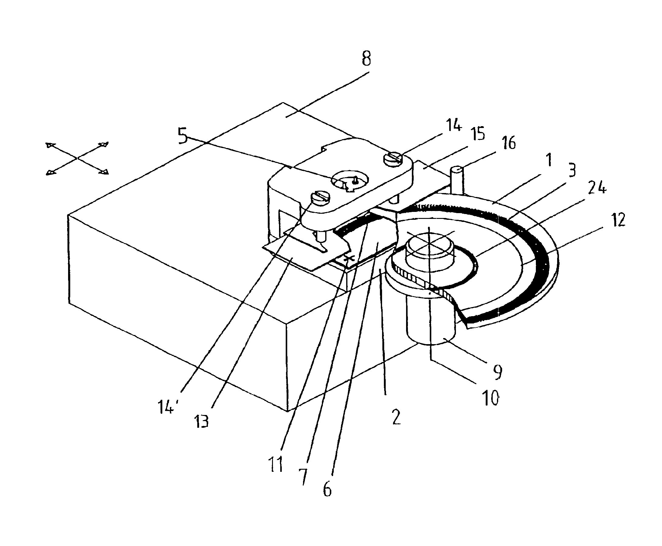
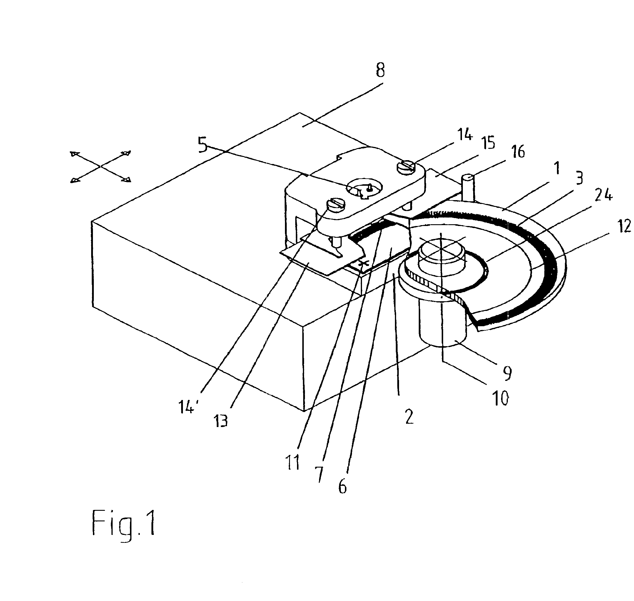
[0054]FIG. 1 (schematically) shows an optical measuring device designed for pre-adjusted mounting, as far as it is required to illustrate the method. Said optical angle-measuring device consists of a pitch disk 1 as a gauge and of a sensing head 2, which senses the pitch structures 3 on the transparent pitch disk 2 according to the transmitted light method in a known manner. The pitch structures 3 are provided as pitches. The sensing head 2 comprises an illuminating unit 5 and a sensing plate 6 having sensing structures 7 thereon, which correspond, in a known manner, to the pitch structures 3 to be sensed. The resulting optical sensing signals are transformed into electrical signals in a conventional and, thus, not represented manner, via photodiodes and further electrical components, said electrical signals being transmitted to a control unit or a counter via electrical lines.

[0055]The sensing head 2, in particular the sensing plate 6 with the sensing structures 7, must be very pre...


PUM


Abstract

The invention relates to a position measuring system for scanning a movement between a first element and a second element which is arranged in a moveable manner in relation to the first element. Said system comprises a material measure which can be fixed to the first element and has a scale carrier, and a scanning head which can be fixed to the second element and which scans a movement of the material measure in relation to the scanning head. The inventive system comprises a mount by which means the material measure and the scanning head can be fixed to each other in a pre-determined position, the scanning head being detachably fixed to the scale carrier. In order to assembly one such position measuring system on a first element and a second element moving in relation thereto, the scanning head is fixed to the material measure in such a way that the scanning head and the material measure are mutually fixed in position. The material measure is then applied to the first element and the scanning head to the second element, the scanning head or the material measure being fixed to the respective element, filling the gap, in the position which is pre-determined by the positioned mount. The mount between the scanning head and the material measure is then detached.

Description

CROSS REFERENCE TO RELATED APPLICATIONS[0001]This application claims priority to PCT Application designating the U.S. Ser. No. PCT / EP01 / 12993, filed on Nov. 9, 2001, incorporated herein by reference, which claims priority to German Application No. 100 56 947.1 filed Nov. 17, 2000, incorporated herein by reference.BACKGROUND OF THE INVENTION[0002]The invention relates to a method for mounting a position measuring system on a first part and on a second part movable relative to said first part, wherein said position measuring system comprises a gauge, which has a pitch carrier and is fixable on said first part, and a sensing head fixable on said second part, said method comprising the steps of fixing the sensing head on the gauge such that the sensing head and the gauge are fixed in position relative to each other, fixing the gauge on the first part and the sensing head on the second part, and releasing said fixation between the sensing head and the gauge. The invention further relates...

Claims


Application Information

Patent Timeline
Patent Type & Authority Patents(United States)
IPC IPC(8): G01D5/347G01D5/26
CPCG01D5/3473G01D5/34707
Inventor FREITAG, HANS-JOACHIMFRANZ, HEINZ-GUENTHERSCHMIDT, ANDREAS
Owner OPTOLAB LICENSING
Why Eureka
Try Eureka