Lubricant still and reservoir for refrigeration system

a technology of lubricant still and reservoir, which is applied in the direction of separation process, lighting and heating apparatus, multiple-effect evaporation, etc., can solve the problems of depletion of lubricant supply for bearing and rotor lubrication, degraded heat transfer efficiency of evaporator, and not always provided fully satisfactory, etc., to achieve high viscosity, increase flow, and high viscosity

Inactive Publication Date: 2005-06-14
CARRIER CORP
View PDF4 Cites 20 Cited by
  • Summary
  • Abstract
  • Description
  • Claims
  • Application Information

AI Technical Summary

Benefits of technology

[0009]It is another object of this invention to provide an improved lubricant still that produces lubricant of high viscosity and maintains high viscosity during operating transients that result in increased flow of oil laden refrigerant from evaporator to still.
[0010]These objects, and others as will become apparent hereinafter, are accomplished by the lubricant still of the present invention for use in a compressor for separating lubricant from refrigerant. The still includes a vessel having an inlet for incoming oil laden refrigerant, an outlet for gaseous refrigerant, and an outlet for refrigerant laden oil. A separating structure is provided for separating transitioning oil laden refrigerant from the incoming oil-laden refrigerant, wherein the oil laden refrigerant progressively changes to refrigerant laden oil closer to the outlet for refrigerant laden oil. A heating device is used for heating the incoming oil laden refrigerant and transitioning oil laden refrigerant, for facilitating the formation of the gaseous refrigerant and the refrigerant laden oil.

Problems solved by technology

As a result, evaporator heat transfer effectiveness is degraded.
Even worse, lubricant supply for bearing and rotor lubrication is eventually depleted.
While oil separators do separate the lubricant, they have not always provided fully satisfactory results.
This lowers its viscosity, degrading its usefulness as a bearing lubricant.
The use of a separator can also cause a pressure drop in the compressed refrigerant, which is undesirable.
A separator may also add considerable cost to the system since it is a pressure vessel of considerable size.
Approaches to achieving higher viscosity lubricants in conventional stills are less than satisfactory.
For example, simply increasing the amount of heat provided to vaporize refrigerant may result in somewhat higher lubricant viscosity but may also incur a severe penalty to system efficiency since the extra heat provided must be accounted for when calculating the system efficiency.
Moreover, conventional stills are defective in producing adequate lubricant viscosity during operating transients that result in sudden increases in the influx rate of oil laden refrigerant from the evaporator.

Method used


Image

  • Lubricant still and reservoir for refrigeration system
  • Lubricant still and reservoir for refrigeration system
  • Lubricant still and reservoir for refrigeration system

Examples


Embodiment Construction

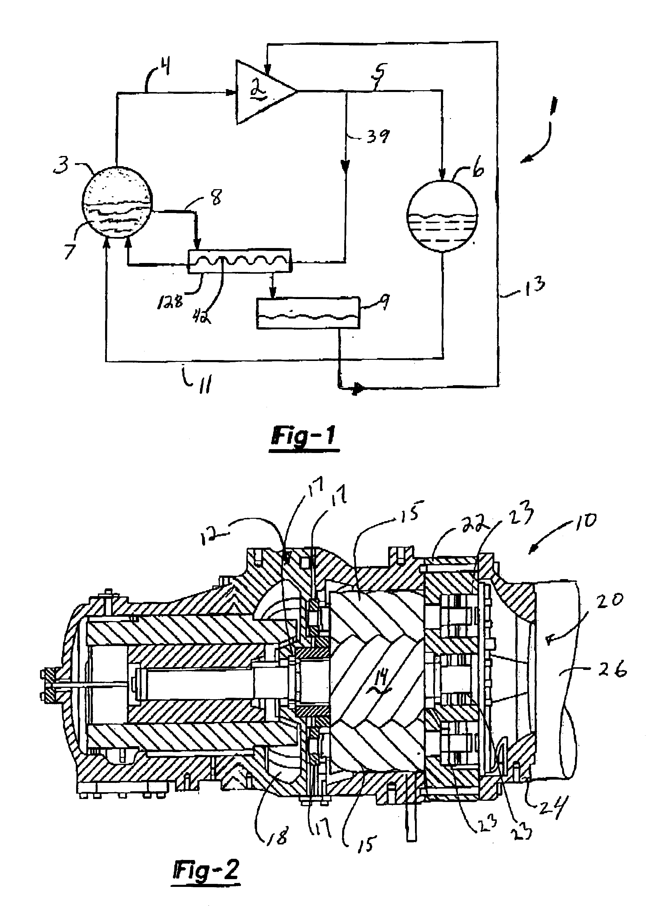
[0020]Referring now to the drawings in detail there is shown in FIG. 1 a schematic view of a refrigerant system 1, including a compressor 2.

[0021]As is known, a flooded style evaporator 3 delivers primarily gaseous refrigerant to the compressor 2 through a line 4. Gaseous refrigerant is compressed by compressor 2, entraining lubricant during its passage through compressor 2 that is used to lubricate the bearings and rotors of compressor 2. From the compressor 2, refrigerant with entrained oil passes through a line 5 to a condenser 6. Compressed gaseous refrigerant is cooled in the condenser, transferred into a liquid phase, with oil in mixture or solution, as it passes in line 11 through an expansion valve (not shown) to evaporator 3. At the evaporator 3, an environment to be cooled is cooled by the refrigerant in the evaporator. As is shown, it is typical that liquid refrigerant 7 settles from the refrigerant in the evaporator. This refrigerant 7 is typically lubricant or oil laden...


PUM


Abstract

A lubricant still for use in a compressor for separating oil from refrigerant, includes a vessel having an inlet for incoming oil laden refrigerant, an outlet for gaseous refrigerant, and an outlet for refrigerant laden oil. A separating structure is provided for separating transitioning oil laden refrigerant from the incoming oil-laden refrigerant, wherein the oil laden refrigerant progressively changes to the refrigerant laden oil closer to the outlet for refrigerant laden oil. A heating device is used for heating the incoming oil laden refrigerant and transitioning oil laden refrigerant, for facilitating the formation of the gaseous refrigerant and the refrigerant laden oil.

Description

TECHNICAL FIELD[0001]This invention is directed to separation of lubricant from refrigerant in compressors, and more particularly, the separation of lubricant from refrigerant in a lubricant still.BACKGROUND OF THE INVENTION[0002]Screw or helical compressors are commonly used in air conditioning applications to compress refrigerant as part of the refrigeration cycle. Screw compressors are composed of meshing screw or helical rotors. While two rotor configurations are the most common design, screw compressors are also known in the art having three, or more, rotors housed in respective overlapping bores so as to co-act in pairs. The rotors of a typical screw compressor are mounted in bearings at each end in housing end plates at the inlet and discharge side. Refrigerant is compressed by the screw rotors toward the discharge side and discharged through ports and into a discharge line.[0003]In normal applications, a solution or mixture of oil and refrigerant is used for lubricating scre...

Claims


Application Information

Patent Timeline
Patent Type & Authority Patents(United States)
IPC IPC(8): B01D1/00B01D1/02B01D1/26F28D3/00
CPCB01D1/0017B01D1/0088F28D3/00B01D1/26B01D1/02
Inventor SHOULDERS, STEPHEN L.
Owner CARRIER CORP
Why Eureka
Try Eureka