
Flow-diverting rotary valves of multiple paths

a rotary valve and flow-diverting technology, applied in the field of rotary valves, can solve the problems of large-sized valves that are inconvenient, limited by the prior art, and complex operation, and achieve the effects of reducing volume differences among the circular grooves, reducing fluid pressure, and reducing volume differences

Inactive Publication Date: 2005-06-14
ARCHIDEX
View PDF7 Cites 27 Cited by
  • Summary
  • Abstract
  • Description
  • Claims
  • Application Information

AI Technical Summary

Benefits of technology

[0007]The present invention describes a rotary valve for simultaneously diverting a plurality of liquid streams among a plurality of liquid receivers in a sequential and cyclic manner. Rather than the prior art that has the circular grooves spacing apart concentrically on the flat surface of the stationary disc, the circular grooves of the present invention locate laterally and are spaced apart longitudinally along a rotating shaft of the rotary valve. The configuration of the present invention has a minimum increase of stator-rotor contacting area and fluid contacting area when an additional circular groove is constructed into the rotary valve, which allows a large number of flow paths and a higher fluid pressure for the rotary valve. The volumes of the circular grooves are minimized and the volume differences among the circular grooves are also eliminated. Said rotary valve comprises:

Problems solved by technology

If multiple flow passages are required to go through the same process simultaneously, as in the case of the simulated moving bed chromatography, the operation is very complex and a special fluid diverting device is needed.
This is due to the inherent limitation of the prior art.
The increase of the disc size results in a large-sized valve that is inconvenient.
The increase of the rotor-stator contacting area means a significant increase of friction that prevents the rotary valve from rotation.
The increase of fluid contact area generates a larger force that pushes the stator disc apart from the rotator disc and impairs the seal between the stator disc and the rotator disc when the fluid has a high pressure.
All these factors restrict the rotary valve of the prior art to a limited number of flow paths (usually four flow paths) and to the applications of low fluid pressures.
Another drawback of the prior art is the relative large volume of the circular grooves and the dramatic volume differences among the circular grooves.

Method used


Image

  • Flow-diverting rotary valves of multiple paths
  • Flow-diverting rotary valves of multiple paths
  • Flow-diverting rotary valves of multiple paths

Examples


Embodiment Construction

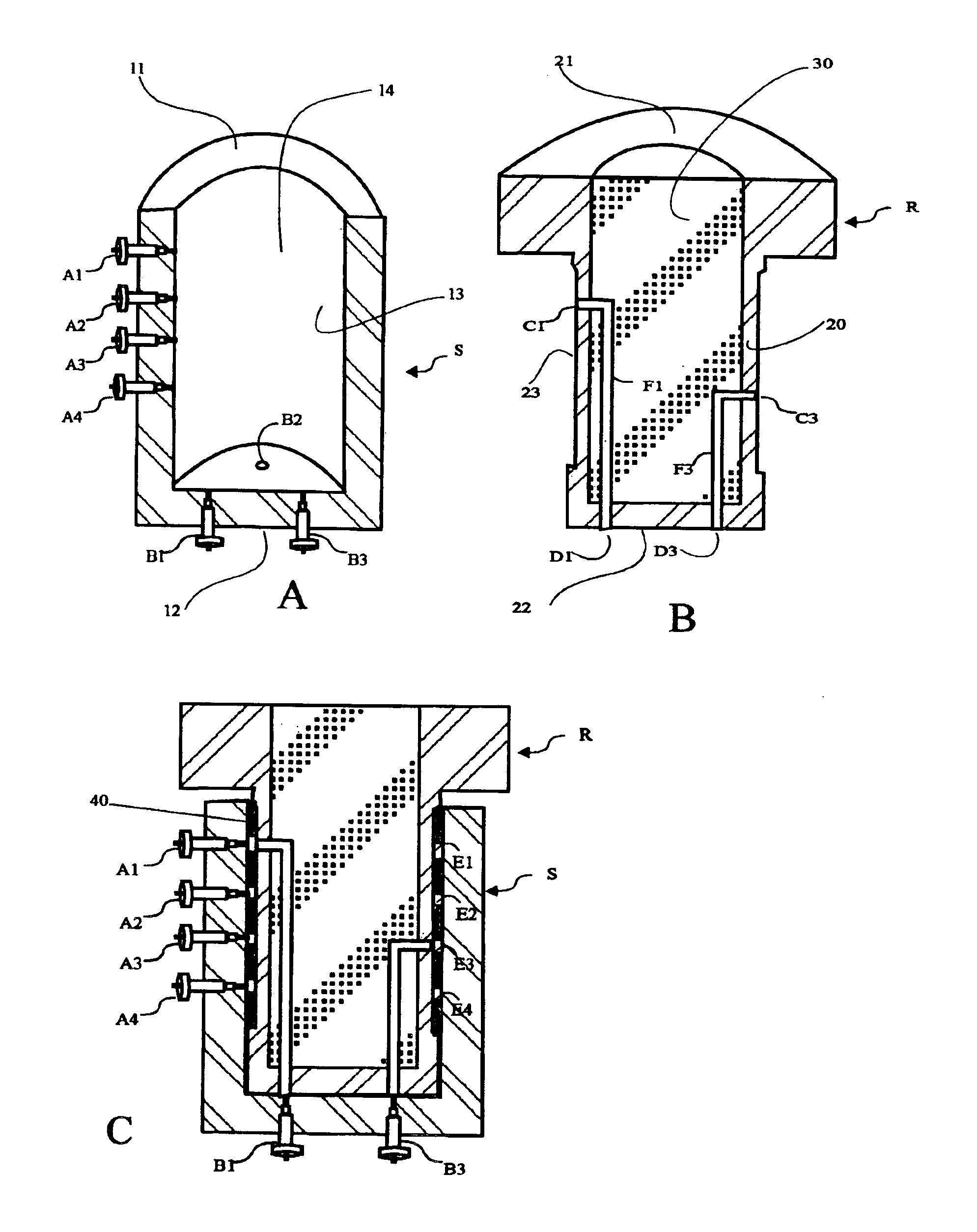
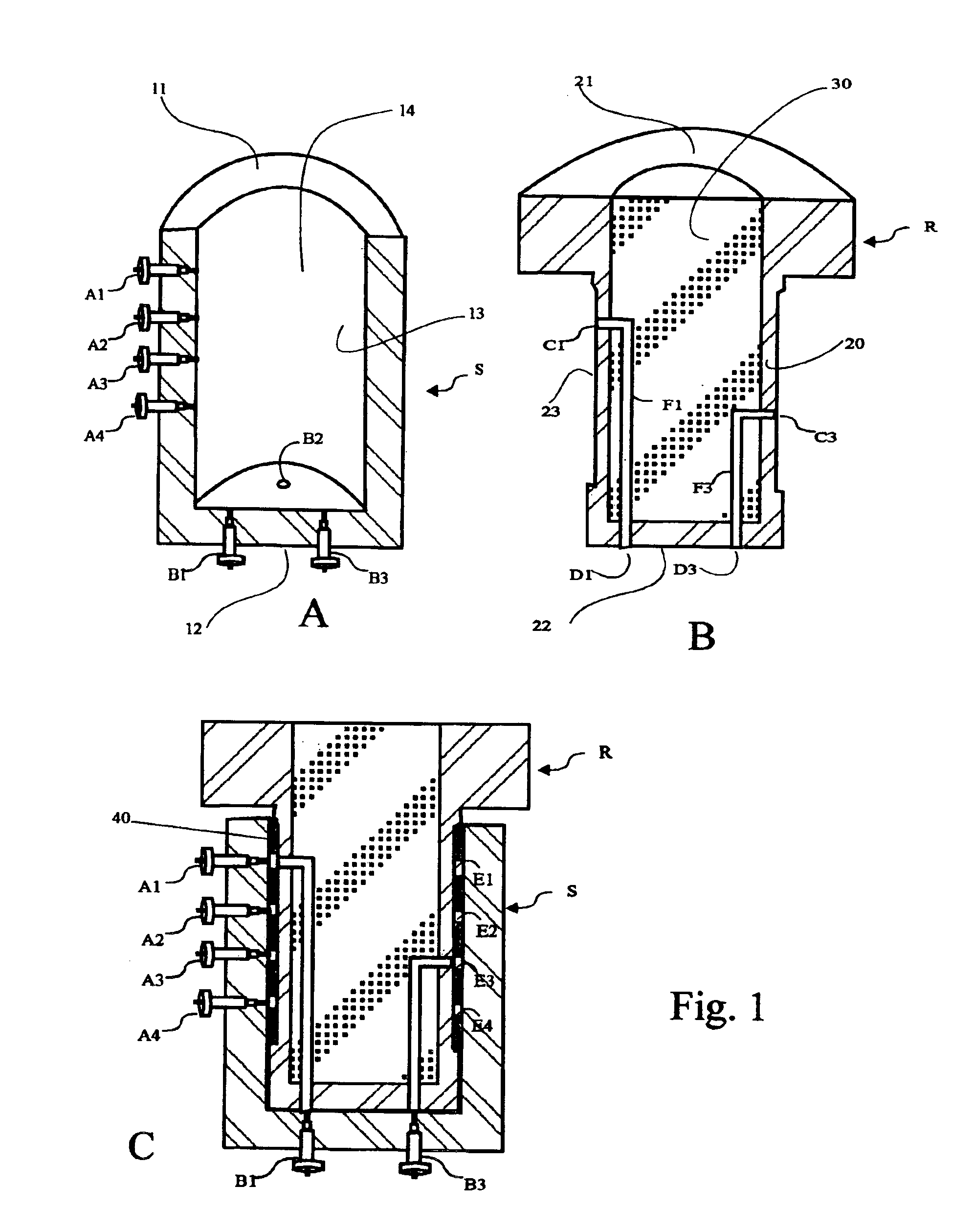
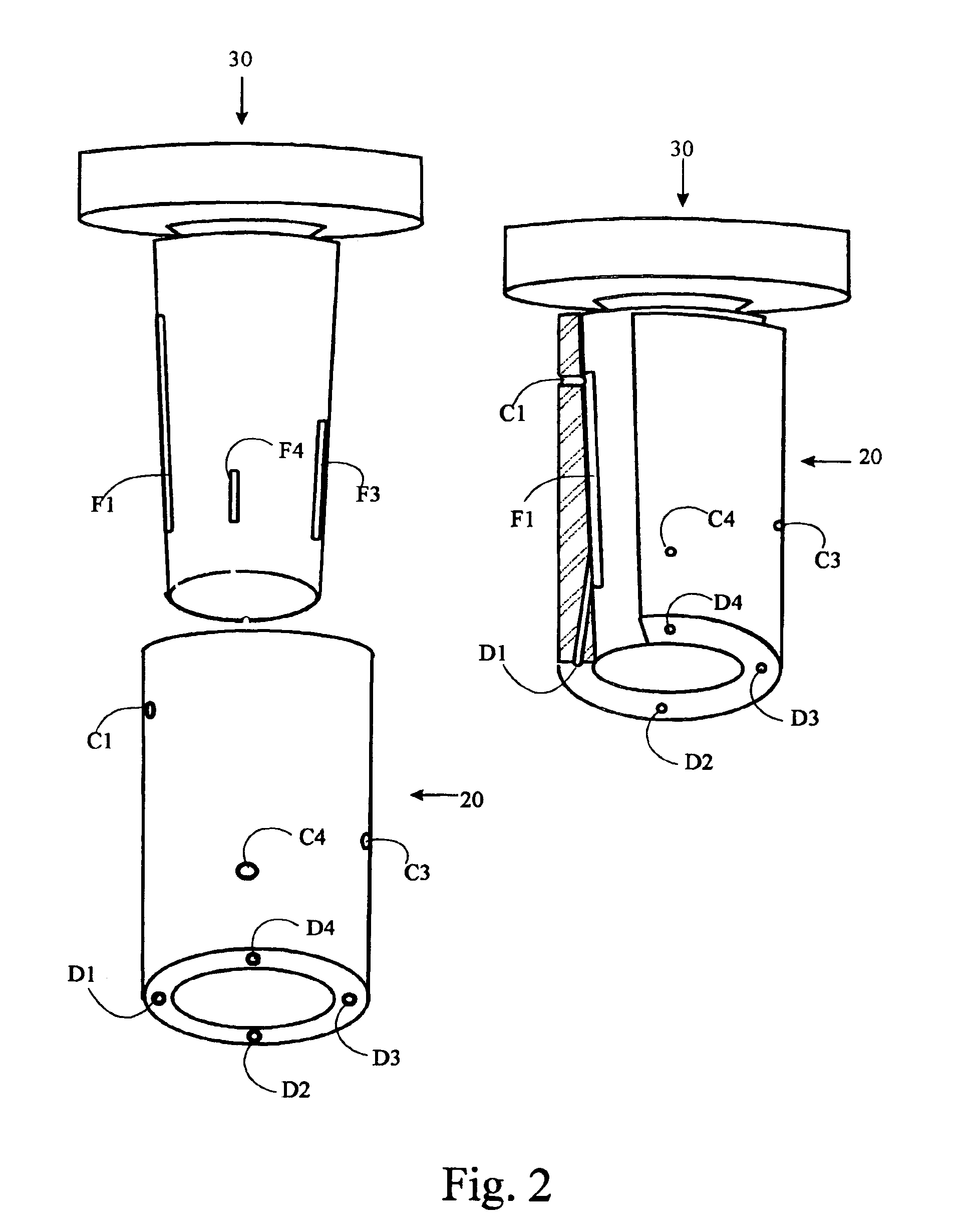
[0018]For exemplary purpose, all Figures for the preferred embodiments have four flow paths for diverting four fluid streams. It should be realized that the valve of the present invention are able to simultaneously divert more fluid streams and the number of flow paths of the valve is not a limit of the present invention.

[0019]FIG. 1 shows one embodiment of the present invention. The embodiment comprises a stator S and a rotor R that is positioned within stator S. Stator S has a top end 11, a bottom end 12, a lateral exterior surface 13, a circular cavity 14 with an lateral interior surface 14a, and a plurality of external ports extending from lateral exterior surface 13 to the lateral interior surface 14a. Said ports are grouped into group A of 4 ports and group B of 4 ports. The ports of group A are designated as port A1 to A4 and are spaced apart longitudinally from said top end 11. Ports of group B are designated as ports B1 to B4, are located approximate to the bottom end 12 on...


PUM


Abstract

The present invention describes a rotary valve for simultaneously diverting a plurality of liquid streams among a plurality of liquid receivers in a sequential and cyclic manner. Said rotary valve comprises: (1) a stator of barrel shape having a circular cavity, a bottom, a lateral structure, a group of first ports being spaced longitudinally along the lateral structure, and a group of second ports being evenly spaced apart on the bottom around the axis of the stator at the same distance from said axis, the number of the second ports being n multiple of that of the first ports wherein n is an integer of 1 or larger; (2) a rotor constructed by a hollow shaft section and a core section within said hollow shaft section, said hollow shaft section having a lateral structure accommodating a plurality of top openings that are longitudinally spaced apart and a bottom end accommodating a plurality of bottom openings that are evenly spaced apart around the axis of the hollow shaft at the same distance from said axis as the distance of the second ports from the axis of the stator, said core structure accommodating a plurality of flow passages that connect the top openings to the corresponding bottom openings; (3) the rotor being assembled in the circular cavity of the stator and a plurality of ring structures being sandwiched in-between the lateral exterior surface of the hollow shaft section of the rotor and the interior surface of said circular cavity and being longitudinally spaced apart, two adjacent ring structures forming one circular groove that is in fluid communication with a corresponding first port of the stator and a corresponding top opening of the rotor, the rotor being rotatable about the axis of said circular cavity, the junction between the exterior surface of the bottom end of the rotor and the interior surface of the bottom of the circular cavity of the stator forming a leak-proof contact with an exception of the bottom openings of the rotor which are in fluid communication with the corresponding second ports of the stator when a stepwise rotation of the rotor is properly indexed, each flow passage constantly being fluidly communicated with a corresponding first port, a top opening, and a bottom opening to form a constant flow path that contains the same fluid regardless of rotation, each second port of the stator receiving a different fluid when the second port is switched away from the currently engaged bottom opening to the adjacent bottom opening by a stepwise rotation, simultaneous diversion of multiple fluids being thus realized.

Description

PRIORITY CLAIM[0001]This application claims benefit of priority of U.S. Provisional Application Ser. No. 60 / 374,237 filed on Apr. 19, 2002 titled “Flow-Diverting Rotary Valves of Multiple Paths”.FIELD OF THE APPLICATION[0002]The present invention relates to a rotary valve for diverting multiple fluids to different receivers in a sequential and cyclic manner.BACKGROUND[0003]In a number of fluid delivery processes, a flow passage is required to sequentially receive n fluids one after another from the 1st fluid to the nth fluid and to repeat the process endlessly in a progressive and cyclic manner. If multiple flow passages are required to go through the same process simultaneously, as in the case of the simulated moving bed chromatography, the operation is very complex and a special fluid diverting device is needed.[0004]U.S. Pat. No. 3,706,812 describes a rotary valve for this process. The rotary valve comprises three basic parts: a stationary disc, a rotating disc, and a stationary ...

Claims


Application Information

Patent Timeline
Patent Type & Authority Patents(United States)
IPC IPC(8): F16K11/083F16K11/076F16K11/02F16K11/06
CPCF16K11/0836F16K11/076Y10T137/86501Y10T137/86871
Inventor MA, QI-FENG
Owner ARCHIDEX
Learn More