Horizontal transmission and oil system for telehandlers

a transmission system and horizontal technology, applied in the direction of electric propulsion mounting, transportation and packaging, jet propulsion mounting, etc., can solve the problem that the weight of the engine cannot be effectively used as a counterweight against a load at the front end of the material handling machin

Inactive Publication Date: 2005-06-14
JLG IND INC
View PDF32 Cites 14 Cited by
  • Summary
  • Abstract
  • Description
  • Claims
  • Application Information

AI Technical Summary

Problems solved by technology

As a result, severe drive shaft angles are created that can cause vibration and wear in the power train.
Additionally, the larger the material handling machine, the more severe the drive shaft angles can be, since the main frames are wider on the larger machines.
Furthermore, since the engine is arranged between the transmission and cooling system, the weight of the engine cannot be effectively used as a counter weight against a load at the front end of the material handling machine, such as a load carried by the boom in the case of a telescopic handler.
Consequently, one of the dr...

Method used


Image

  • Horizontal transmission and oil system for telehandlers
  • Horizontal transmission and oil system for telehandlers
  • Horizontal transmission and oil system for telehandlers

Examples


Embodiment Construction

[0028]While the invention is open to various modifications and alternative forms, a specific embodiment thereof has been shown by way of example in the drawings and will herein be described in detail. There is no intent to limit the invention to the particular form disclosed.

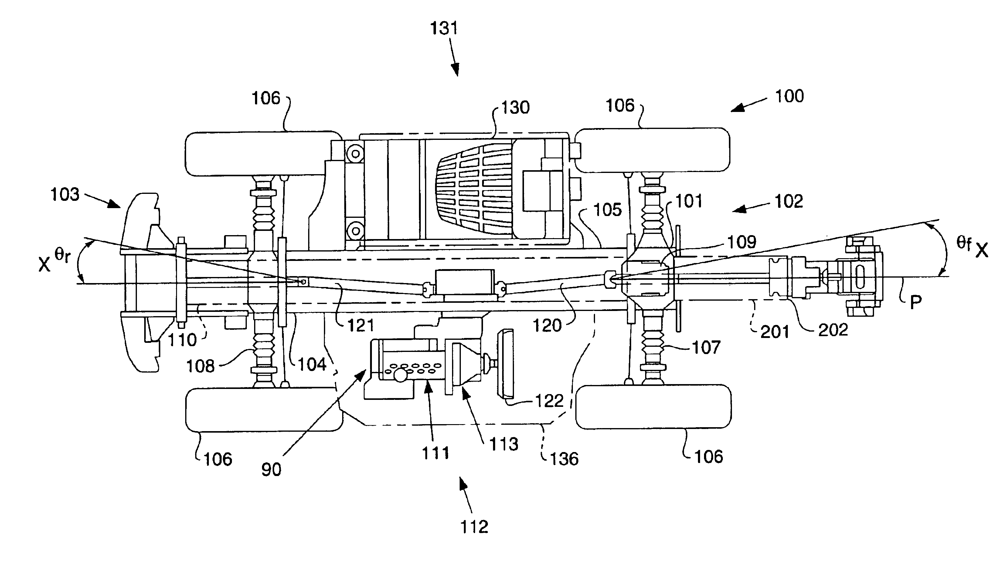
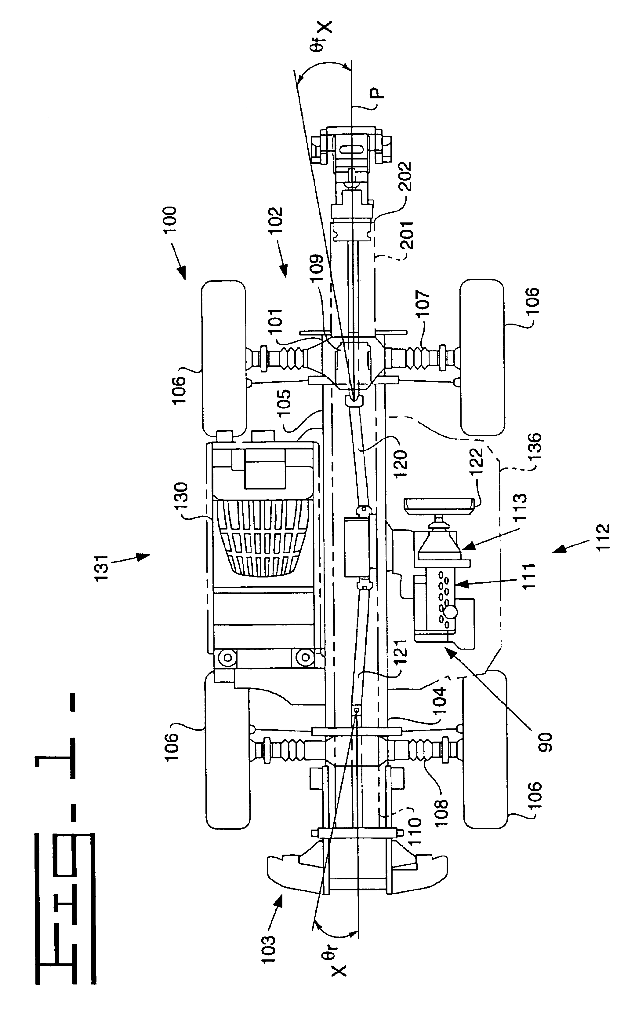
[0029]Referring to FIGS. 1-3, a power train arrangement for a work machine 100, according to an embodiment of the invention, is indicated generally at 90. The work machine 100 includes a chassis or main frame 101 having a front end 102 and a rear end 103 with a longitudinal axis X—X extending between the front end 102 and the rear end 103 and passing through a longitudinal vertical center plane P of the work machine 100. The main frame 101 has an elongated configuration defined by first and second substantially parallel and spaced apart side members 104, 105, which are oriented vertically.

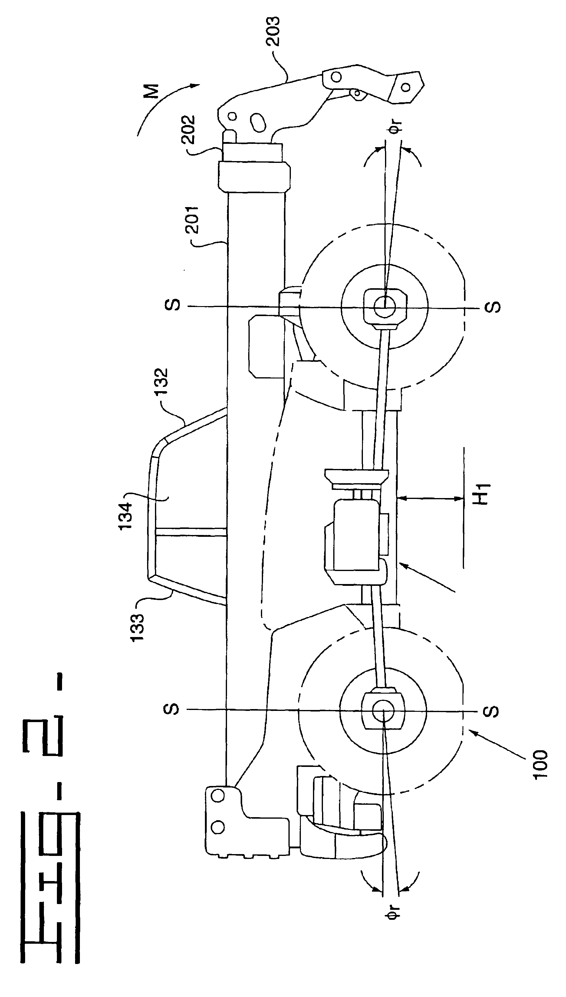
[0030]Seen specifically in FIGS. 1 and 2, the work machine 100 is a telescopic handler having a telescopic boom 201 that is p...


PUM


Abstract

A power train arrangement having a prime mover and a transmission coupled to the prime mover for driving a cooling system with the prime mover through the transmission. The transmission is positioned intermediate to the prime mover and the cooling system in a manner to optimize the mechanical and functional operation of the work machine.

Description

[0001]This application claims the benefit of prior provisional patent application Ser. No. 60 / 332,845, filed Nov. 16, 2001.TECHNICAL FIELD[0002]This invention relates to a power train arrangement, and more particularly to a power train arrangement for work machines, such as material handling machines.BACKGROUND[0003]Work machines such as material handling machines for use at construction sites typically have large diameter front and rear wheels driven by a power train. These material handling machines are designed to carry out given tasks such as digging, loading, or pallet-lifting. The relatively large wheels place a constraint on the arrangement of the machine's power train components and operator's cabin.[0004]One known material handling machine for use at construction sites is a telescopic handler. This machine has an elongated main frame defined by first and second substantially parallel and vertically oriented side members that are spaced apart to form a longitudinally extendi...

Claims


Application Information

Patent Timeline
IPC IPC(8): B60K11/02B60K17/04B60K17/34B66F9/065E02F9/08
CPCB60K11/02B60K17/04E02F9/0866B66F9/0655B66F9/07595B60K17/34
Inventor COUTANT, ALAN R.DANIEL, STEVEN A.GRIFFITHS, ALAN J.KEANE, LIAM W.
Owner JLG IND INC
Why Eureka
Try Eureka