Preparation method of in situ double-tilt electronic microscope sample rod

A technology of electron microscope samples and sample rods, which is applied in the direction of circuits, discharge tubes, electrical components, etc., can solve the problems of expensive, difficult to modify, and immature products, etc., and achieve low manufacturing costs, mature equipment, and fill the gaps in the market Effect

Active Publication Date: 2012-07-04
QINGDAO UNIV
View PDF2 Cites 13 Cited by
  • Summary
  • Abstract
  • Description
  • Claims
  • Application Information

AI Technical Summary

Problems solved by technology

Although purchasing ready-made sample holders has many advantages over self-made sample holders, it is expensive, making it difficult to modify it to suit the special needs of the experiment
In addition, the introduction of optical signals to the sample has always been a tricky problem
With the advancement of optical fiber and microlens technology, many research groups have begun to design in-situ sample rods that can introduce optical signals, but there are no mature products to choose from.

Method used


Image

  • Preparation method of in situ double-tilt electronic microscope sample rod
  • Preparation method of in situ double-tilt electronic microscope sample rod
  • Preparation method of in situ double-tilt electronic microscope sample rod

Examples


Embodiment

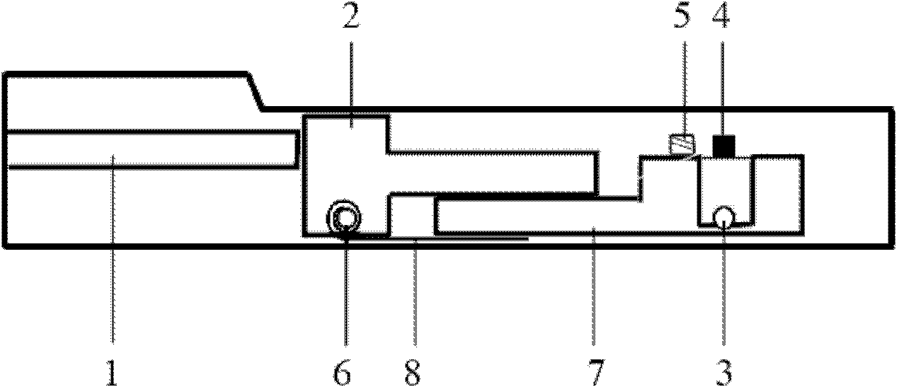
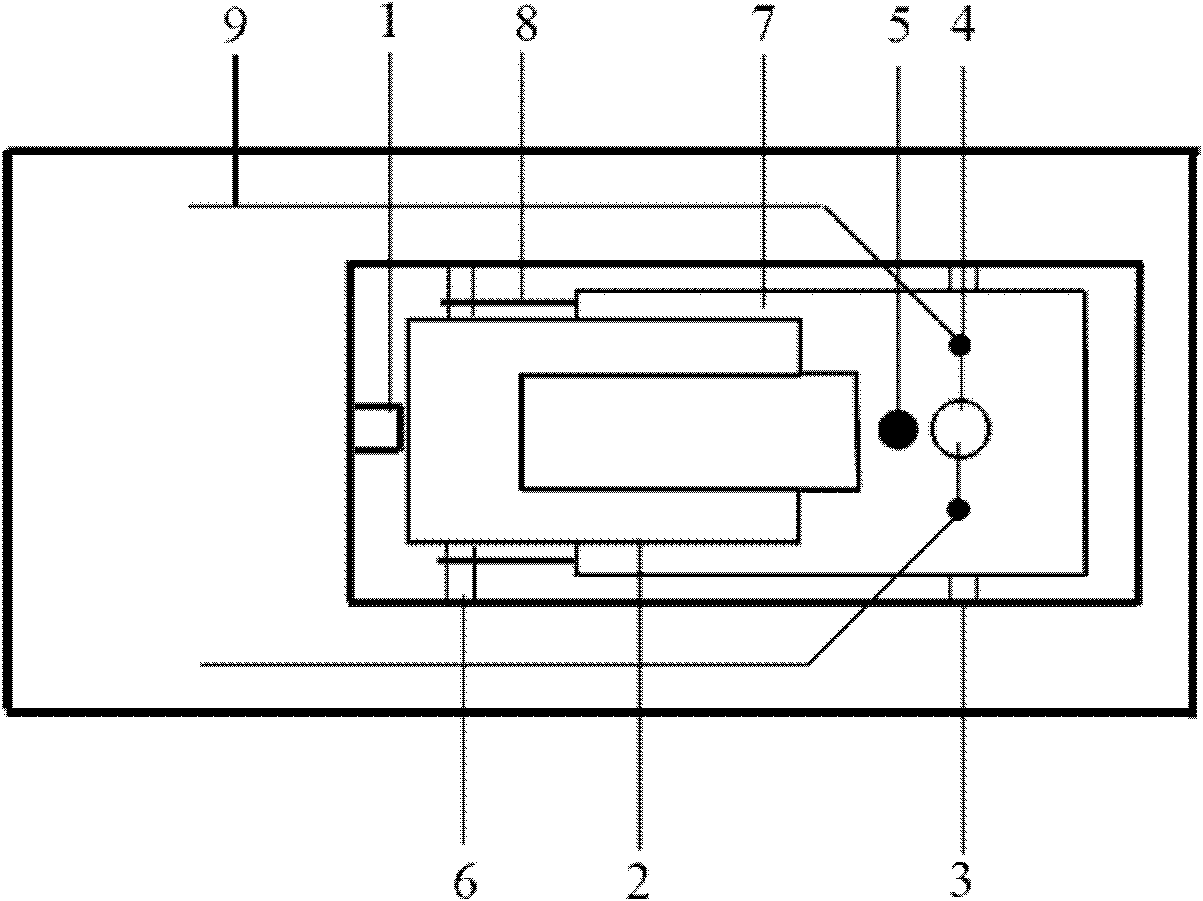
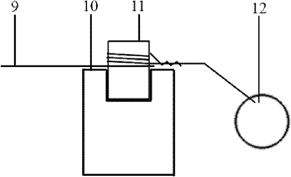
[0014] The process steps of this embodiment include in-situ double-tilt sample rod design, electric field component installation and optical fiber access, wherein the in-situ double-tilt sample rod design is based on the existing single-tilt electron microscope sample rod, and the hollow copper of the sample rod Open up three independent sealing passages in the rod, which are respectively assigned to the horizontal transmission rod 1, the wire 9 and the optical fiber, and respectively seal the horizontal transmission rod 1 with a special sealing ring for transmission electron microscopy, and seal the optical fiber and the wire 9 with epoxy resin. The side view and top view of the front end of the in-situ double-tilt sample rod are shown in Fig. figure 1 and figure 2 As shown; the X-axis tilt of the sample rod is realized by the goniometer of the electron microscope itself; the Y-axis tilt drives the horizontal transmission rod 1 to move in the horizontal direction through a s...


PUM


Abstract

The invention belongs to the technical field of material analysis and testing, and relates to a manufacturing method of an in situ double-tilt electronic microscope sample rod for which an electric field and a light signal can be added externally; the method comprises the following steps that: first, three independent channels are arranged in a hollow copper bar of a sample rod based on an existing single-title electronic microscope sample rod in an insulated and closed way; the three independent channels are respectively distributed to a horizontal transmission rod, a lead and an optical fiber and are insulated and sealed; the sample rod tilts rotationally along a Y axis through a stepper motor which is arranged outside the sample rod and is connected with the horizontal transmission rod; then an electric field terminal is arranged on a sample cup and is more than 10cm away from an optical axis, so that the concentration of charge and the affection of the imaging quality are prevented; then an optical fiber fixed column is arranged on the sample cup, metal is sprayed onto the surface of a transmitting optical fiber and the optical fiber is connected in, and a laser led-in sample is formed into an in situ transmission double-tilt sample rod; and according to the preparation method of the in situ double-tilt electronic microscope sample rod, a design idea is novel, the used equipment and technologies are mature, the manufacturing cost is low, the market blank is filled, experimental needs are met, and the practicality and test results are good.

Description

Technical field: [0001] The invention belongs to the technical field of material analysis and testing, and relates to a method for preparing an in-situ double-tilt transmission electron microscope sample rod capable of applying an electric field and an optical signal, which is used for preparing electron microscope samples when testing samples. Background technique: [0002] With the advancement of modern testing technology and the increasing research of materials science, the study of in-situ electron microscopy has become one of the main directions of electron microscopy development, and a large number of research results have emerged in recent years. A number of electron microscope manufacturers have launched their own sample holders for in-situ research, and the growing research demand even gave birth to high-tech companies (such as the famous Nanofactory, etc.) that specialize in the manufacture of various in-situ sample holders. Most of the current ones that can be pur...

Claims


Application Information

Patent Timeline
Patent Type & Authority Applications(China)
IPC IPC(8): H01J37/20
Inventor 王乙潜谭金山梁文双杜庆田
Owner QINGDAO UNIV
Why Eureka
Try Eureka