Nut rotating ball screw pair transmission unit

A ball screw pair and nut rotation technology, which is applied in the field of ball screws, can solve the problems of high noise in the transmission process, difficulty in installing the rack, and the length of the screw can not be too long, so as to ensure positioning accuracy, simple and compact structure, and design The effect of novel ideas

Inactive Publication Date: 2013-04-03
TIANSHUI METALFORMING MACHINE TOOL GROUP
View PDF10 Cites 7 Cited by
  • Summary
  • Abstract
  • Description
  • Claims
  • Application Information

AI Technical Summary

Problems solved by technology

This transmission method has the following disadvantages: 1. Poor positioning accuracy and repetitive positioning accuracy during the transmission process; 2. Low transmission speed; 3. High noise during the transmission process; 4. High processing costs for gears and racks; 5. Difficult rack installation , segmented seams are of poor quality
The ball screw with this structure is relatively difficult to process, and the length of the screw should not be too long, otherwise the stability will be poor, resulting in low transmission accuracy

Method used


Image

  • Nut rotating ball screw pair transmission unit
  • Nut rotating ball screw pair transmission unit
  • Nut rotating ball screw pair transmission unit

Examples


Embodiment Construction

[0015] Below in conjunction with accompanying drawing, the present invention is described in further detail:

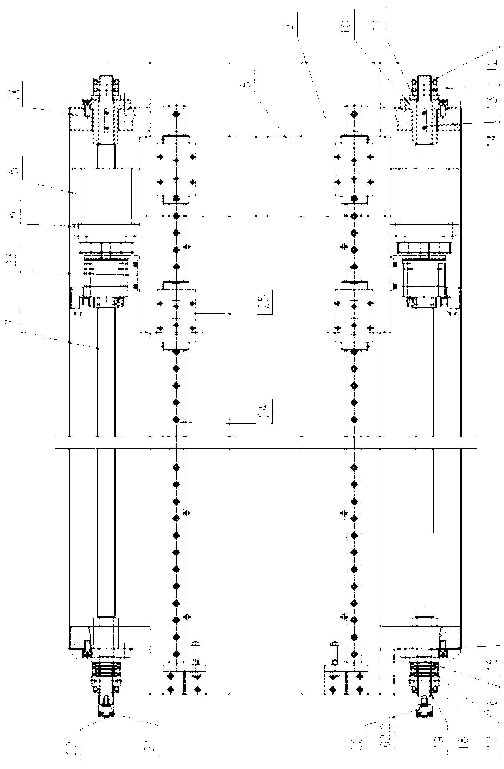
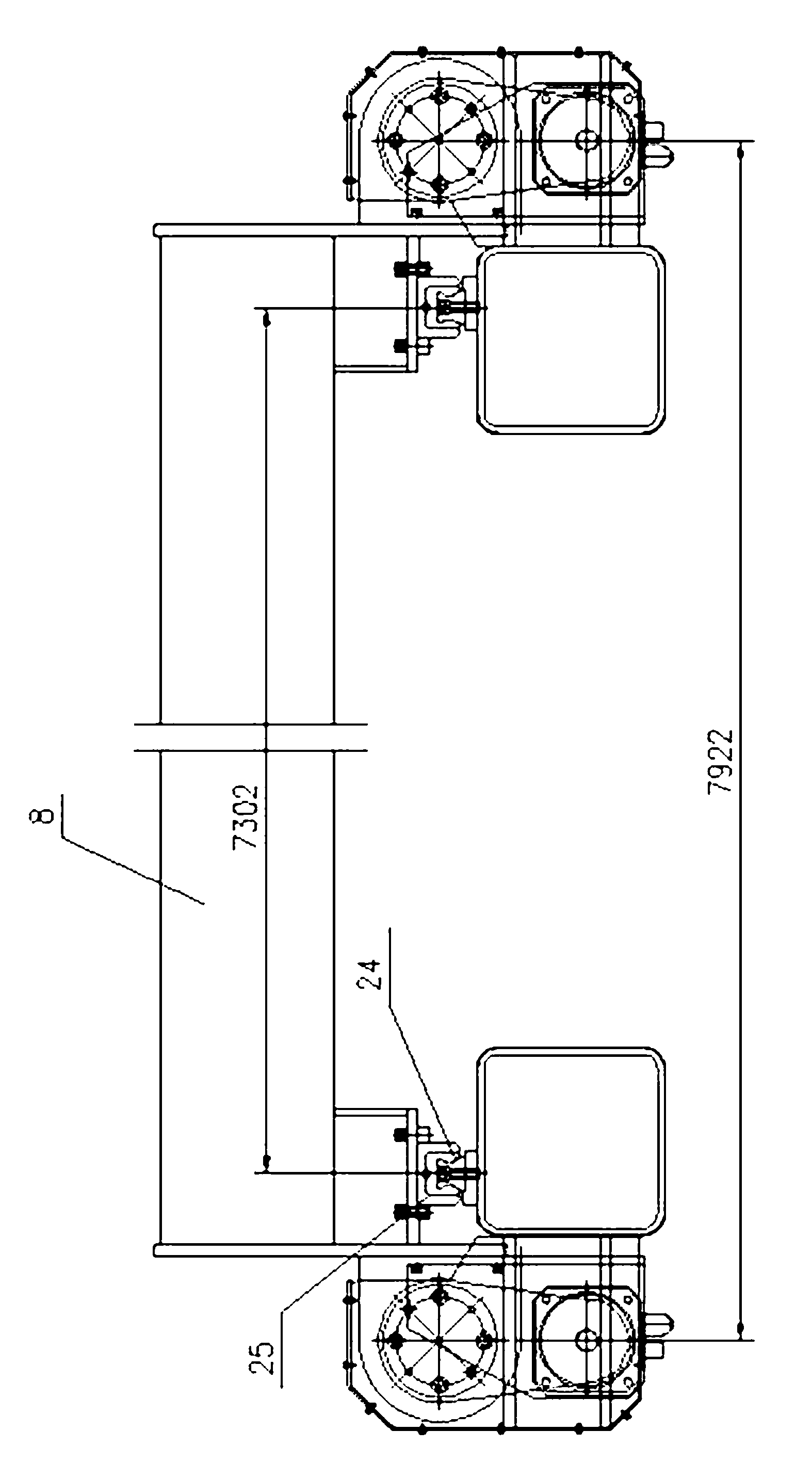
[0016] Such as figure 1 , 2 , As shown in 3, a nut rotating ball screw auxiliary transmission unit includes a fixed bracket 9, a servo motor 1, a ball screw 7, and a feeding beam 8. The feeding beam 8 is an integrally welded rectangular cross-section beam, with nut seats 5 welded at both ends for installing ball screw auxiliary nuts 6, and the distance between centers of the nut seats 5 is 7922mm. Servo motor brackets 23 are respectively installed at both ends of the feeding beam 8, and roller sliders 25 are installed on the bottom surface of the feeding beam 8. Here, a double slider structure is adopted, with 2 sliders arranged on one side, and the center distance of the sliders is 7302㎜ . The fixed brackets 9 are arranged symmetrically at both ends of the feeding beam 8 respectively, and the linear guide rails 24 are installed on the fixed brackets 9 . The rolle...


PUM


Abstract

The invention discloses a nut rotating ball screw pair transmission unit which comprises fixed brackets, a servo motor, ball screw pairs, linear guide rails and a feeding beam, wherein the fixed brackets are symmetrically arranged on two ends of the feeding beam, the linear guide rails are arranged on the upper part of the fixed brackets, roller type slide blocks are arranged on the linear guide rails, the feeding beam is arranged on the roller type slide blocks, lead screw seat plates are arranged on the upper parts of the fixed brackets, ball lead screws are arranged on the lead screw seat plates through fixing devices, ball lead screw pair nuts are sleeved on the ball lead screws and are connected with nut seats, the nut seats are connected with the feeding beam, two ends of the feeding beam are connected with a servo motor bracket, and the servo motor is arranged on the servo motor bracket. The nut rotating ball screw pair transmission unit provided by the invention has a simple and compact structure, and is novel and special in design thought. A ball lead screw transmission system is used for replacing a gear-rack transmission mode in an overlong stroke feeding process, and the difficulty of poor feeding precision caused by axial and radial runout in an overlong distance conveying process is solved. High-speed feeding and returning of a plate are realized, and locating precision and repeated locating precision are ensured.

Description

technical field [0001] The invention relates to the technical field of ball screws, in particular to a nut-rotating ball screw auxiliary transmission unit for high-precision plate feeding under high-speed and heavy-load conditions in a flexible numerically controlled metal plate automatic shearing production line. Background technique [0002] In the flexible CNC sheet metal automatic shearing production line, the transmission process of ultra-long stroke sheet metal usually adopts gear and rack transmission. But this kind of transmission process is generally: servo motor drive - gear, rack drive - feeding beam (often fixedly connected with the gear) moves back and forth to realize the feeding positioning function. The rack is installed on the fixed frame, which is generally installed in sections and fixed with a pin shaft. This transmission method has the following disadvantages: 1. Poor positioning accuracy and repetitive positioning accuracy during the transmission proce...

Claims


Application Information

Patent Timeline
Patent Type & Authority Applications(China)
IPC IPC(8): B23D33/02F16H25/22
Inventor 何应东朱广庆吕毓军万运成杨丽娜
Owner TIANSHUI METALFORMING MACHINE TOOL GROUP
Why Eureka
Try Eureka