Mechanical flat rotating disk

A flat-rotating, mechanical technology, applied in metal processing machinery parts, metal processing equipment, feeding devices, etc., can solve the problems of high maintenance cost, complex structure, high machine tool manufacturing cost, and achieve the effect of high precision, simple and compact structure

Inactive Publication Date: 2009-12-16
YUNNAN CY GRP
View PDF0 Cites 14 Cited by
  • Summary
  • Abstract
  • Description
  • Claims
  • Application Information

AI Technical Summary

Problems solved by technology

[0002] Many of the current CNC flat rotary table designs are based on the purpose of meeting the general purpose of various machine tools. The structure is complex and powerful, and the servo power source is used, which is expensive.
Some special-purpose machine tools are aimed at specific processing parts, and the processing accuracy requirements of the parts are not particularly high. Only ordinary flat rotary discs can meet the processing requirements. However, due to the limited optional accessories, these complicated and expensive machines have to be installed. The CNC flat rotary table leads to high manufacturing cost of the machine tool, and the structure is complicated, and the maintenance cost is also high

Method used


Image

  • Mechanical flat rotating disk
  • Mechanical flat rotating disk

Examples


Embodiment Construction

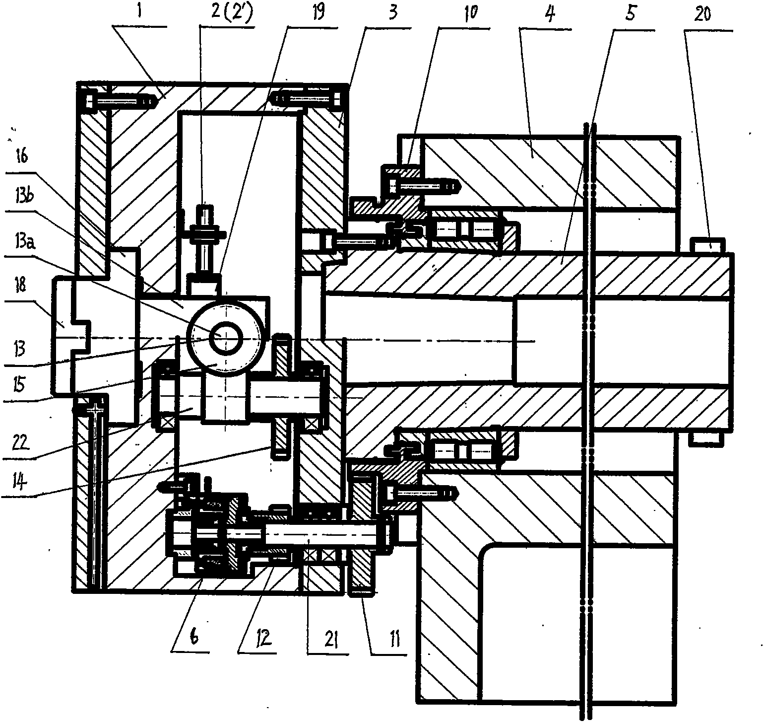
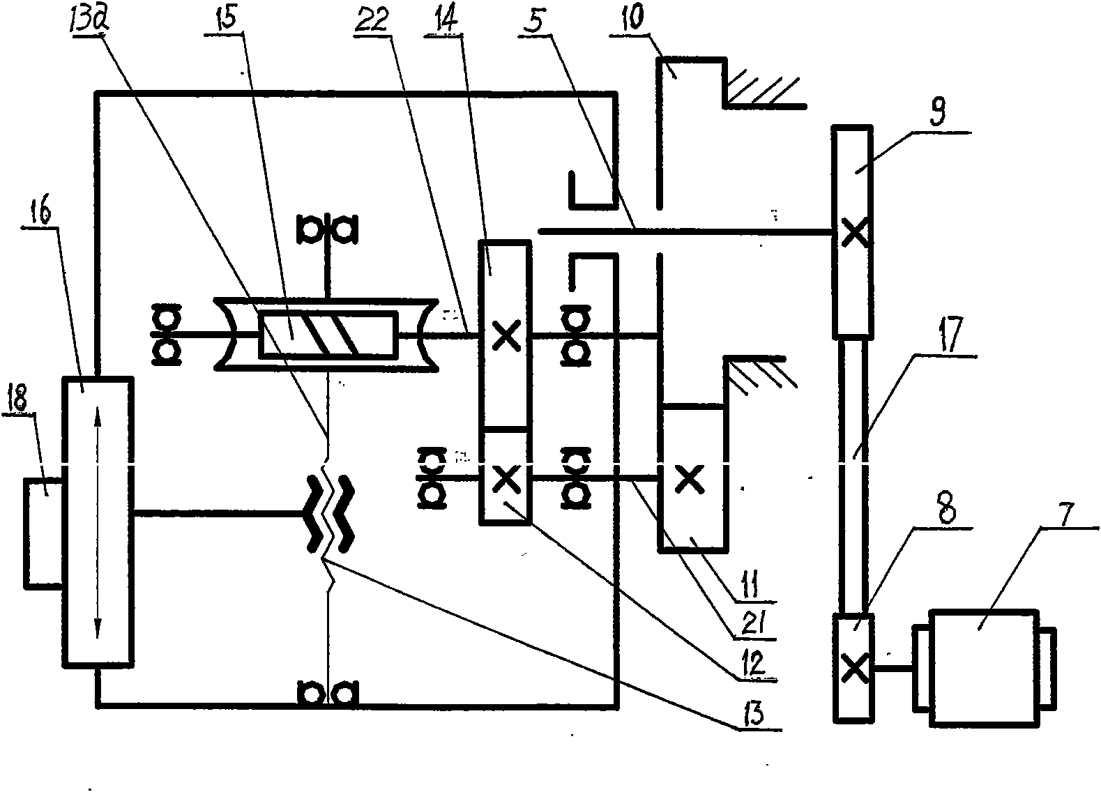
[0011] As shown in the figure, the present invention includes a main motor 7 connected to the driving pulley 8, the driving pulley 8 is connected to the driven pulley 9 through a multi-rib belt 17, and the main shaft 5 is fixed with the driven pulley 9 and the flange 3 , the fixed gear 10 is fixed on the headstock 4 , and the planetary gear 11 meshes with the fixed gear 10 and can rotate around the fixed gear 10 . The planetary gear 11 , the driving gear 12 and the clutch 6 are fixed on the central shaft 21 . A horizontal transmission shaft 22 and a screw pair 13 perpendicular to the transmission shaft are arranged in the flange 3, a worm gear pair 15 is connected to the transmission shaft and a driven gear 14 is installed, and the driving gear 12 meshes with the driven gear 14 , The worm pair 15 is connected to the screw pair 13 through the screw 13a, the slide plate 16 is connected to the screw nut 13b of the screw pair, and can also be fixedly connected to the flange 3 thro...


PUM


Abstract

The invention provides a mechanical flat rotating disk. The disk comprises a horizontal spindle (5) which is arranged in a spindle box (4) and has one end in external connection with a transmission mechanism, wherein the other end of the spindle is fixedly provided with a flange (3); a fixed gear (10) concentric with the spindle is arranged on the spindle box; a planetary gear (11) meshing with the fixed gear is arranged outside the fixed gear; a horizontal transmission shaft (22) and a leadscrew pair (13) perpendicular to the transmission shaft are arranged in the flange; the transmission shaft is connected with a worm gear pair (15) and provided with a driven gear (14); the worm gear pair and the leadscrew pair are connected through a leadscrew; a driving gear (12) and a clutch (6) are arranged on a central shaft (21) of the planetary gear; the driving gear meshes with the driven gear; the outer end of the flange is fixedly connected with a sliding plate (16); and a tool holder (18) is arranged on the sliding plate. The disk has the advantages of simple structure, convenient maintenance, low manufacturing cost and capability of meeting the demand of special machine tools.

Description

technical field [0001] The invention belongs to the technical field of a special accessory for a machine tool—a flat rotary disk structure. Background technique [0002] Many of the current CNC flat rotary table designs are based on the purpose of meeting the general purpose of various machine tools, with complex structures and powerful functions, and the use of servo power sources is expensive. Some special-purpose machine tools are aimed at specific processing parts, and the processing accuracy requirements of the parts are not particularly high. Only ordinary flat rotary discs can meet the processing requirements. However, due to the limited optional accessories, these complicated and expensive machines have to be installed. The CNC flat rotary table leads to high manufacturing cost of the machine tool, and the structure is complicated, and the maintenance cost is also high. Contents of the invention [0003] The purpose of the present invention is to provide a mechani...

Claims


Application Information

Patent Timeline
Patent Type & Authority Applications(China)
IPC IPC(8): B23Q5/34
Inventor 董钟慧曹愭沈曙东宋平刘芸赵明星冯翔徐丽李剑
Owner YUNNAN CY GRP
Why Eureka
Try Eureka