
Cross-flow differential migration classifier

a technology of differential migration and classifier, which is applied in the direction of gas current separation, sedimentation settling tank, and separation process, etc., can solve the problems of reducing the capability of particle/sample separation in liquid, using prior art techniques, and reducing the ability of particle separation, so as to increase the cross sectional area of the flow, increase the field strength, and reduce the flow velocity

Active Publication Date: 2005-06-14
CALIFORNIA INST OF TECH
View PDF7 Cites 52 Cited by
  • Summary
  • Abstract
  • Description
  • Claims
  • Application Information

AI Technical Summary

Benefits of technology

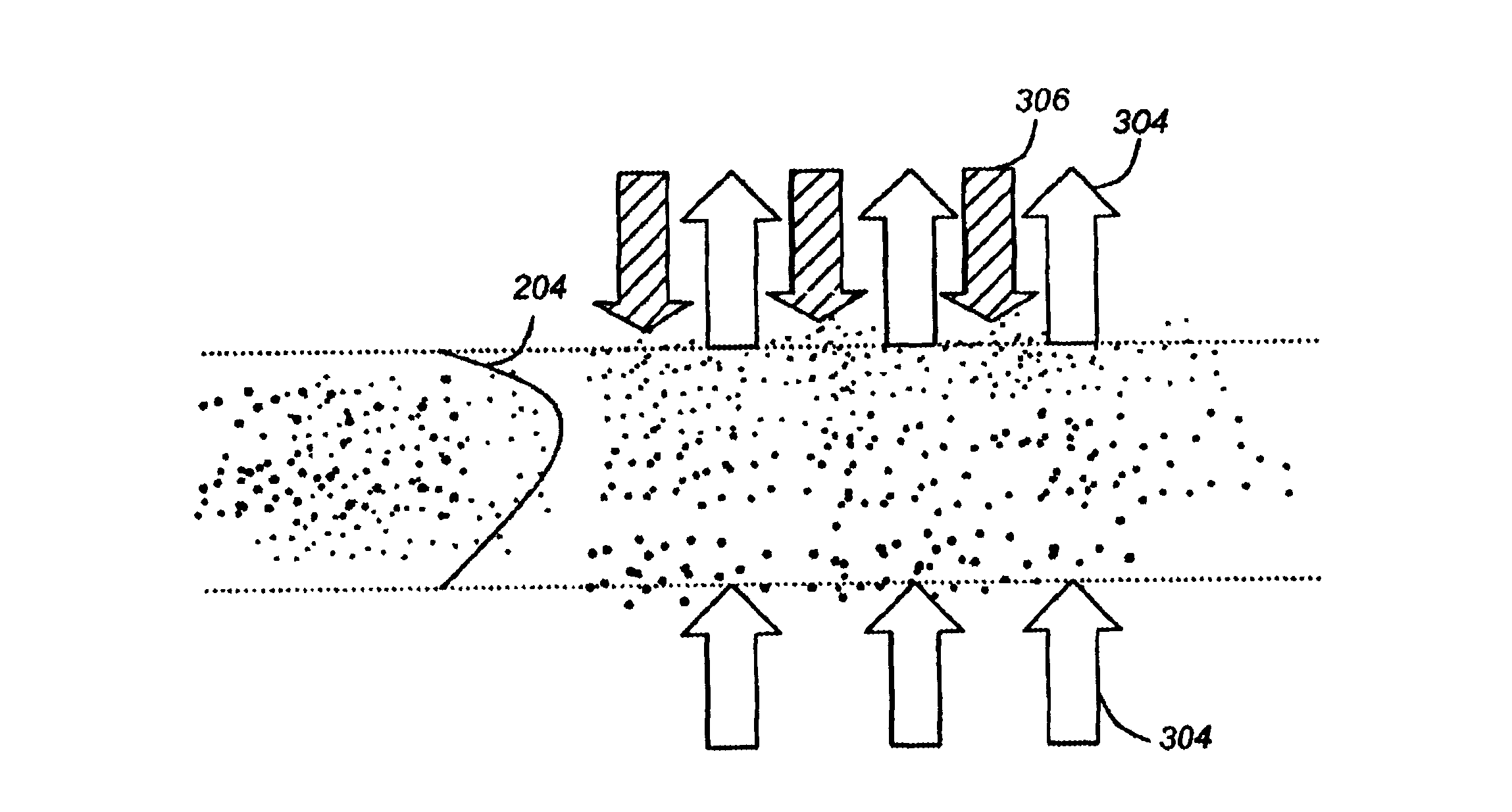
[0041]To counteract this effect, an imposed field is introduced that causes some particles to migrate counter to the flow. The imposed field is counter to the cross-flow and is orthogonal (or has an orthogonal component) to the direction of the sample flow. Thus, the imposed field causes appropriate particles in the sample to remain entrained in the sample flow and to continue to migrate between the walls of the channel.
[0043]In addition, if the particles are allowed to migrate through the wall, provision may be taken to remove the particles from the cross flow so that that fluid can be recirculated. Such provisions may include filtration of the fluid after it exits the channel, and increasing the field strength or reducing the flow velocity (by increasing the cross sectional area of the flow) on the inlet side of the channel so that the applied field causes particles to continue to migrate until they reach a surface where they adhere or are otherwise removed from the fluid.

Problems solved by technology

However, various limitations exist for using the prior art techniques including but not limited to production of a low particle / sample separation ratio, reduced capabilities for separations of particles in a liquid, and a low throughput of a classified sample.

Method used


Image

  • Cross-flow differential migration classifier
  • Cross-flow differential migration classifier
  • Cross-flow differential migration classifier

Examples


Embodiment Construction

[0049]In the following description, reference is made to the accompanying drawings which form a part hereof, and which is shown, by way of illustration, several embodiments of the present invention. It is understood that other embodiments may be utilized and structural changes may be made without departing from the scope of the present invention.

Details of Cross Flow Migration Classifier

[0050]One or more embodiments of the invention provide a method, apparatus, and article of manufacture that enables the continuous separation of particular aerosol, colloidal, and / or suspension particles (e.g., in an aqueous or non-aqueous environment) from a larger input flow. Embodiments introduce simplifications that may dramatically reduce the cost of the separation, by enabling smaller and / or simpler instruments to be made, or to increase the throughput by enabling larger separators to be fabricated.

[0051]FIGS. 3A and 3B illustrates a differential migration classifier in accordance with one or m...


PUM

PropertyMeasurementUnit
Temperatureaaaaaaaaaa
Angleaaaaaaaaaa
Centrifugal forceaaaaaaaaaa

Abstract

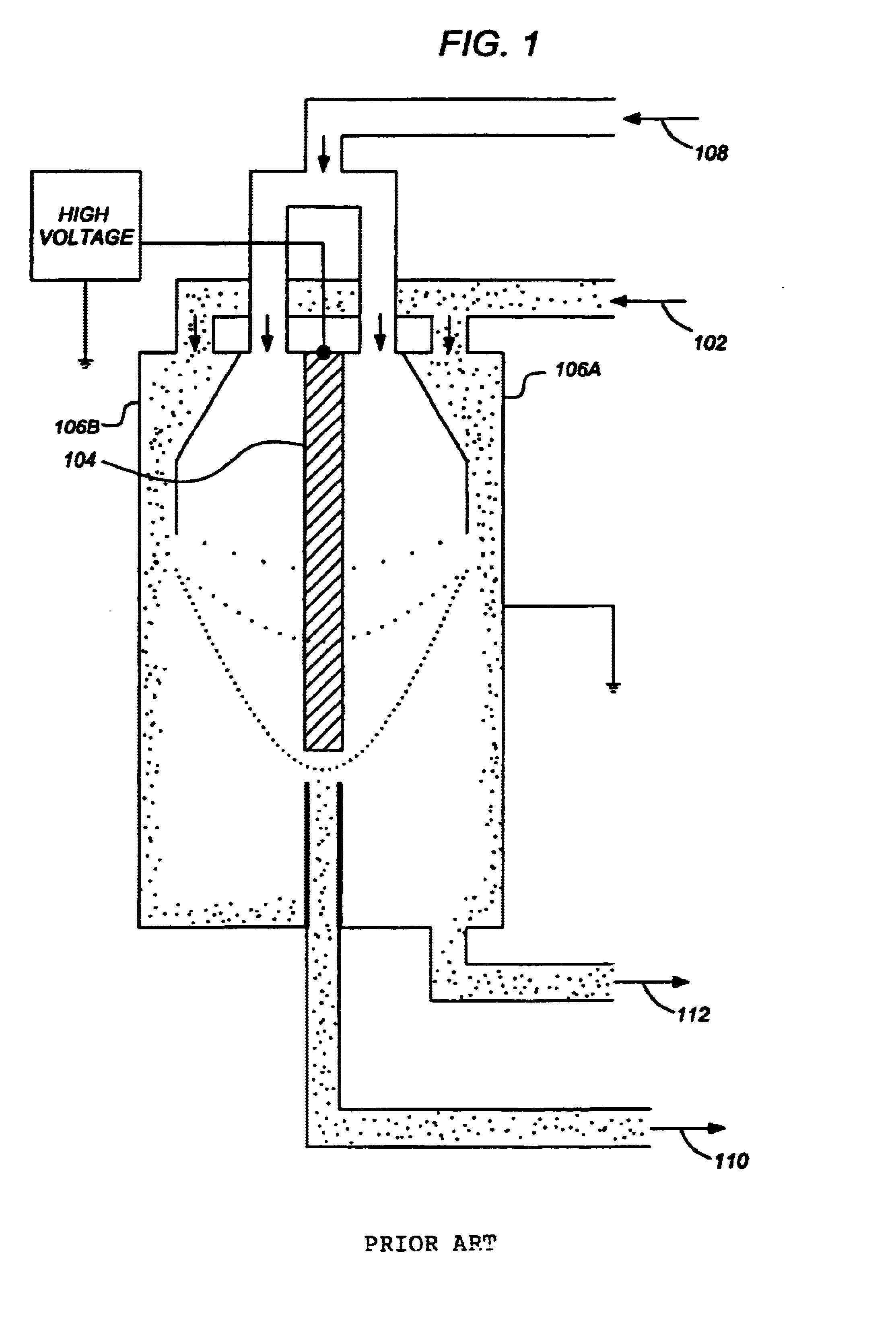
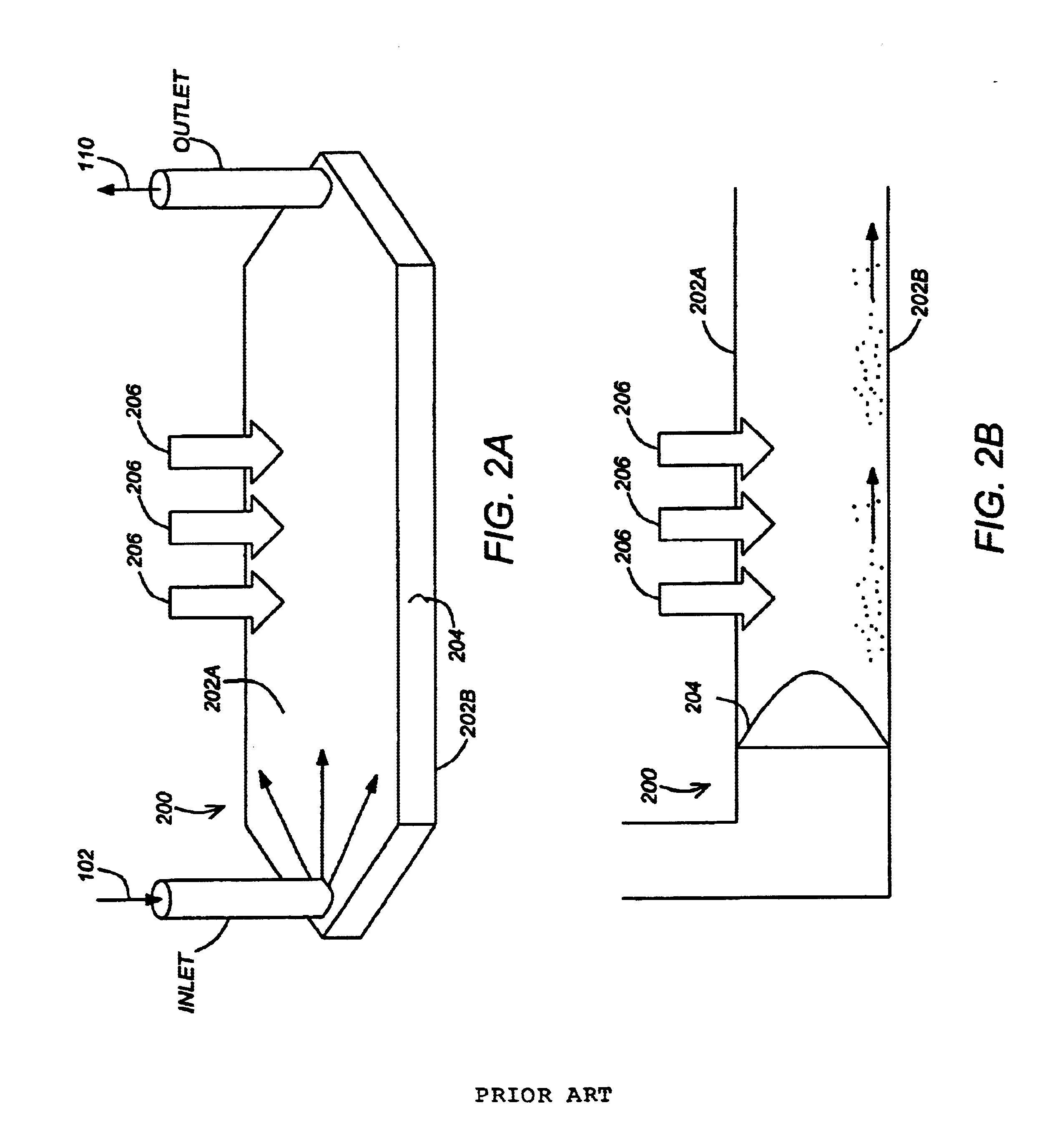
A method, system, apparatus, and article of manufacture provide a cross-flow migration classifier capable of separating particles. The classifier provides a channel through which a sample, having one or more particles, passes in a first direction, wherein the channel comprises two or more walls that are permeable to a flow of fluid. A cross-flow enters the channel through one of the permeable walls and exits through another of the permeable walls. An imposed field is applied in a second direction that is counter to the cross-flow and having an orthogonal component to the first direction. The imposed field causes one or more of the particles to migrate at a first velocity opposite and / or equal to a second velocity of the cross-flow. The particles that migrate opposite to the cross-flow are continuously discharged from the cross-flow migration classifier.

Description

CROSS-REFERENCE TO RELATED APPLICATIONS[0001]This application claims the benefit under 35 U.S.C. Section 119(e) of the following co-pending and commonly-assigned U.S. provisional patent application(s), which is / are incorporated by reference herein:[0002]Provisional Application Ser. No. 60 / 410,070, filed on Sep. 12, 2002, by Richard C. Flagan, entitled “CROSS-FLOW DIFFERENTIAL ELECTRICAL MOBILITY CLASSIFIER,”.BACKGROUND OF THE INVENTION[0003]1. Field of the Invention[0004]The present invention relates generally to separating and measuring particles (including molecules) (e.g., in gases [aerosols] or in liquids [colloids or suspensions]), and in particular, to using a cross-flow differential migration classifier to separate and / or measure particles.[0005]2. Description of the Related Art[0006]The need to separate and measure particles (e.g., particles contained in gases [aerosols] [also referred to as atmospheric ultrafine particles] or in liquids [colloids or suspensions]) according ...

Claims


Application Information

Patent Timeline
IPC IPC(8): B01D21/00B03C1/02B03C1/035B03C3/36B03C3/34
CPCB01D21/0009B03C3/36B03C1/035
Inventor FLAGAN, RICHARD C.
Owner CALIFORNIA INST OF TECH
Learn More