Optical connector cleaning tool

a cleaning tool and optical connector technology, applied in the field of optical connector cleaning tools, can solve the problems of insufficient cleaning operation, difficult to check whether the cleaning tool is working properly, and insufficient cleaning operation, so as to achieve efficient cleaning operation, improve cleaning efficiency, and clean up the effect of sufficien

Inactive Publication Date: 2005-06-14
THE FUJIKURA CABLE WORKS LTD
View PDF3 Cites 26 Cited by
  • Summary
  • Abstract
  • Description
  • Claims
  • Application Information

AI Technical Summary

Benefits of technology

[0018]According to the above optical connector cleaning tool, because the unused portion of the tape is sequentially supplied to the head element from the supply reel, and the used portion of the tape after abutting against the connecting end face of the optical connector is sequentially retrieved by the winding reel, a portion of the cleaning element abutted against the connecting end face can be constantly maintained in clean condition; therefore, an efficient cleaning operation can be achieved.
[0019]In the above optical connector cleaning tool, if the head element is adapted so that the direction of the abutting surface with respect to the direction of insertion of the insertion portion is adjustable, the direction of the abutting surface of the head element can be aligned with the direction of the connecting end face of the optical connector even though the direction of the connecting end face of the optical connector is not aligned with the direction of insertion of the insertion portion; therefore, efficiency of cleaning may be improved.
[0020]In the above optical connector cleaning tool, the insertion portion may preferably comprise a recess for preventing interference with a projecting element (e.g., a guide pin in an MPO type optical connector, which will be explained below) projecting from the connecting end face. Accordingly, cleaning can be sufficiently performed by abutting the cleaning element against the connecting end face even though there is a projecting element on the connecting end face.

Problems solved by technology

Because the connecting end face to be cleaned is disposed at the back of the connector insertion hole and is very difficult to see, it is difficult to check whether the cleaning tool is sufficiently abutted against the connecting end face, or how much of the cleaning operation has been performed; therefore, the cleaning operation may not be sufficiently performed.
Moreover, if the cleaning tool contacts the inner wall of the connector housing, the cleaning tool may become contaminated, and if the contaminated tool is abutted against the connecting end face, the connecting end face may become contaminated or may be damaged during cleaning.
Therefore, the cleaning tool must be carefully inserted, which forces an operator to perform a difficult cleaning operation.
On the other hand, if the optical connector to be cleaned is removed from the connector housing, the connecting end face is easy to see, and it is easy to abut the cleaning tool against the connecting end face; however, the optical connector must be carefully inserted into the connector housing after cleaning so as not to become contaminated with dirt or dust again, which, in addition to detaching and attaching operation for the optical connector, leads to a problem due to very complicated operation.
In the case of cleaning a plug-adapter-plug connecting type optical connector, complicated and low efficiency operation is required if cleaning must be performed after the optical connectors (plugs) respectively inserted into the optical connector adapter from either side thereof are removed from the optical connector adapter.
However, in general, conventional tools are specialized for specific types of connector housings such as an optical connector adapter, several kinds of cleaning tools must be prepared in the workshop so as to be able to deal with several types of connector housings such as an optical connector adapter, which is disadvantageous in terms of workability and cost.
Furthermore, even in the case of using a cleaning tool whose tip portion to be inserted into the connector housing is replaceable, the replacement operation is generally very time consuming, and an enormous effort is required to frequently replace the tip portion of the cleaning tool to be inserted into the connector housing in the workshop, depending on the types of connector housings, which is not practical.

Method used


Image

  • Optical connector cleaning tool
  • Optical connector cleaning tool
  • Optical connector cleaning tool

Examples


first embodiment

[0057]The present invention will be explained in detail below based on the

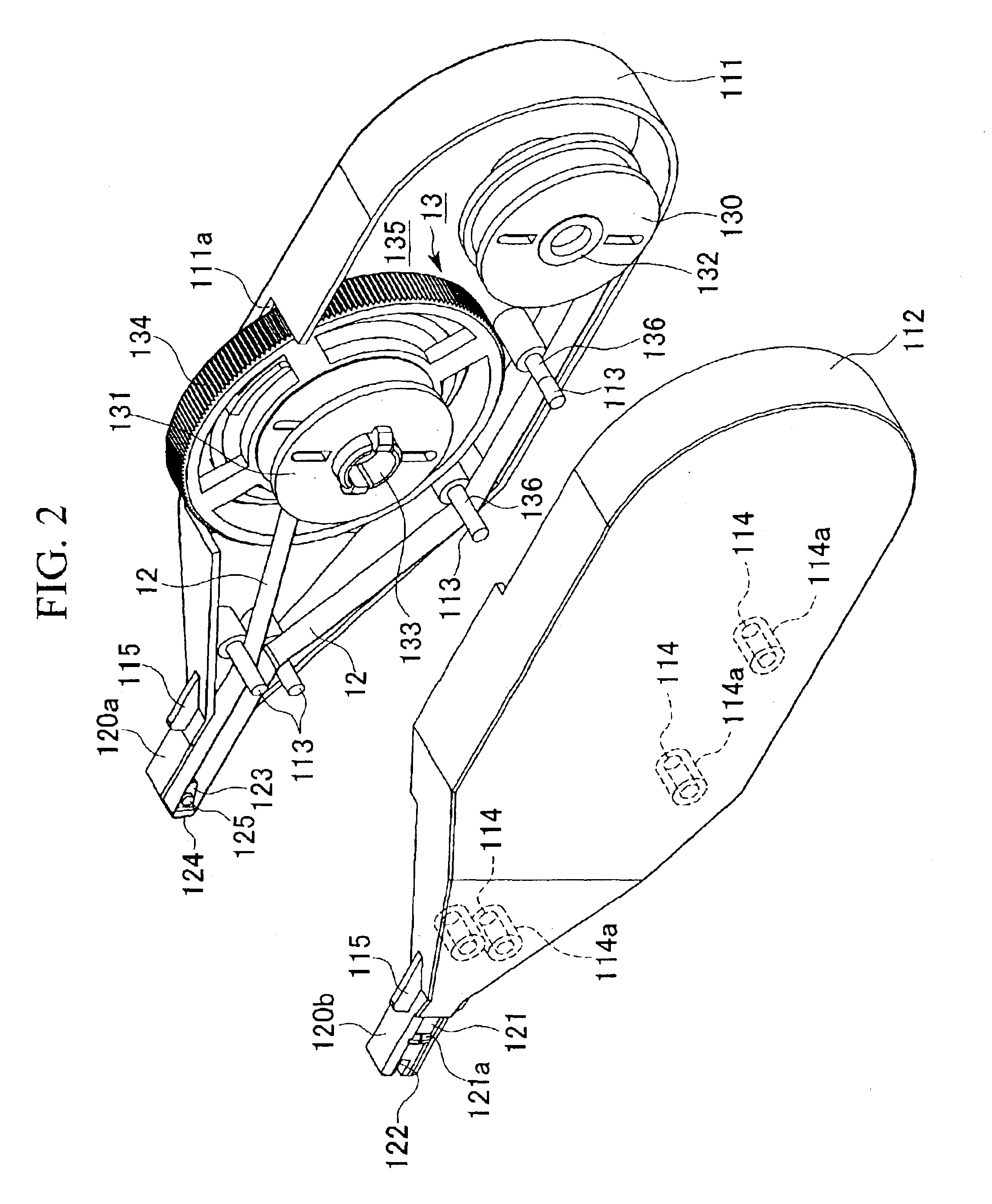
[0058]FIGS. 1A and 1B are respectively a perspective view and a side view showing an optical connector cleaning tool (hereinafter referred to as a cleaning tool) according to the first embodiment, and FIG. 2 is a perspective view showing a state in which the tool body of the cleaning tool is split into halves.

[0059]FIG. 3 is an exploded perspective view showing a state in which an insertion portion of the cleaning tool is going to be inserted into a connector insertion hole of a connector housing in which an optical connector is accommodated, FIG. 4 is a perspective view showing a state in which the insertion portion has been inserted into the connector insertion hole, and FIG. 5 is a cross-sectional view showing a state in which the insertion portion has been inserted into the connector insertion hole.

[0060]FIGS. 6A and 6B are respectively a longitudinal and transverse cross-sectional views showing the vicini...

second embodiment

[0117]Next, the present invention will be explained below with reference to the drawings.

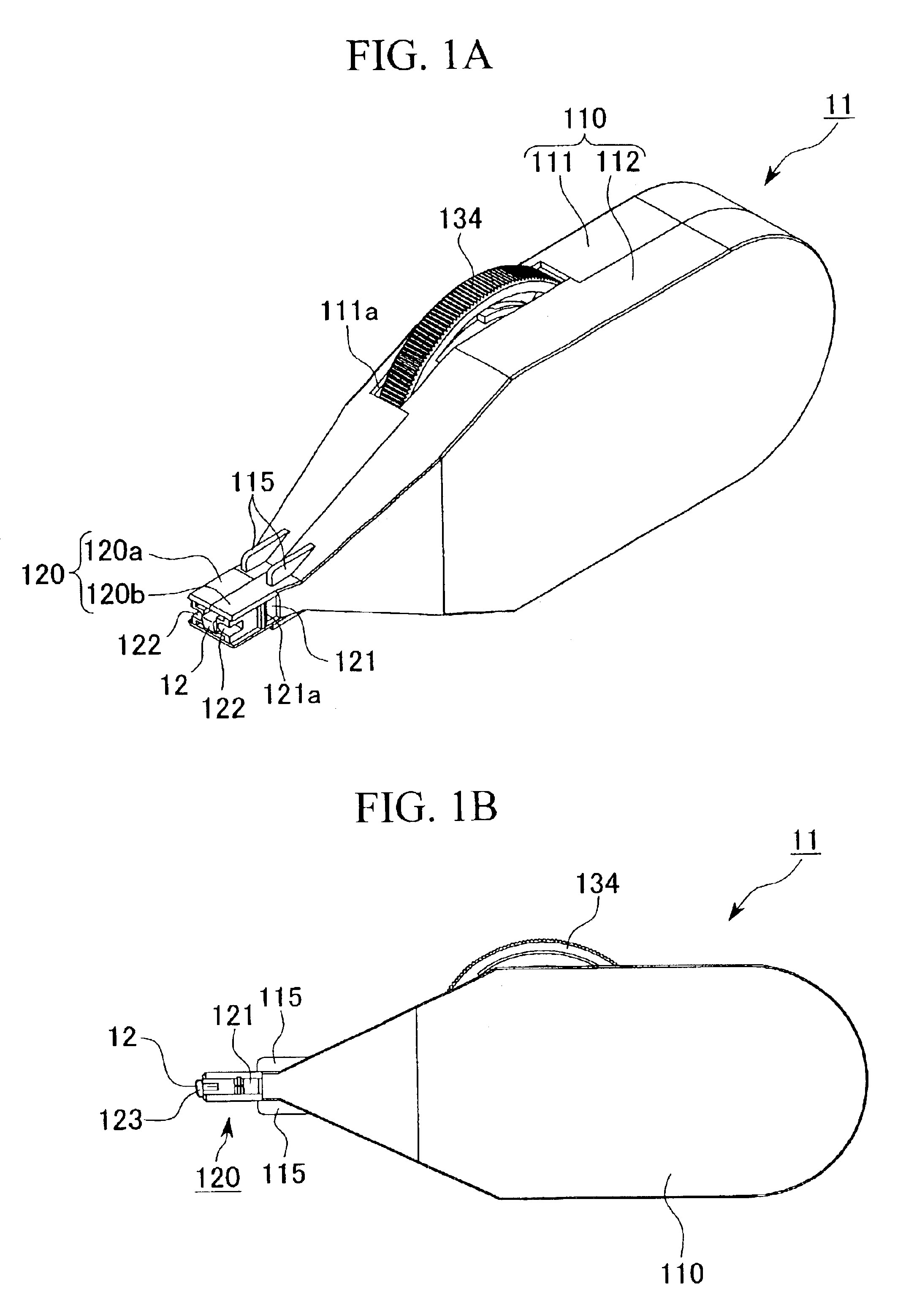
[0118]FIGS. 11A, 11B, and 11C are drawings showing an optical connector cleaning tool of the second embodiment, in particular, FIG. 11A is a perspective view showing the entirety thereof, FIG. 11B is a side view, and FIG. 11C is a partially enlarged perspective view showing a tip portion of the cleaning tool.

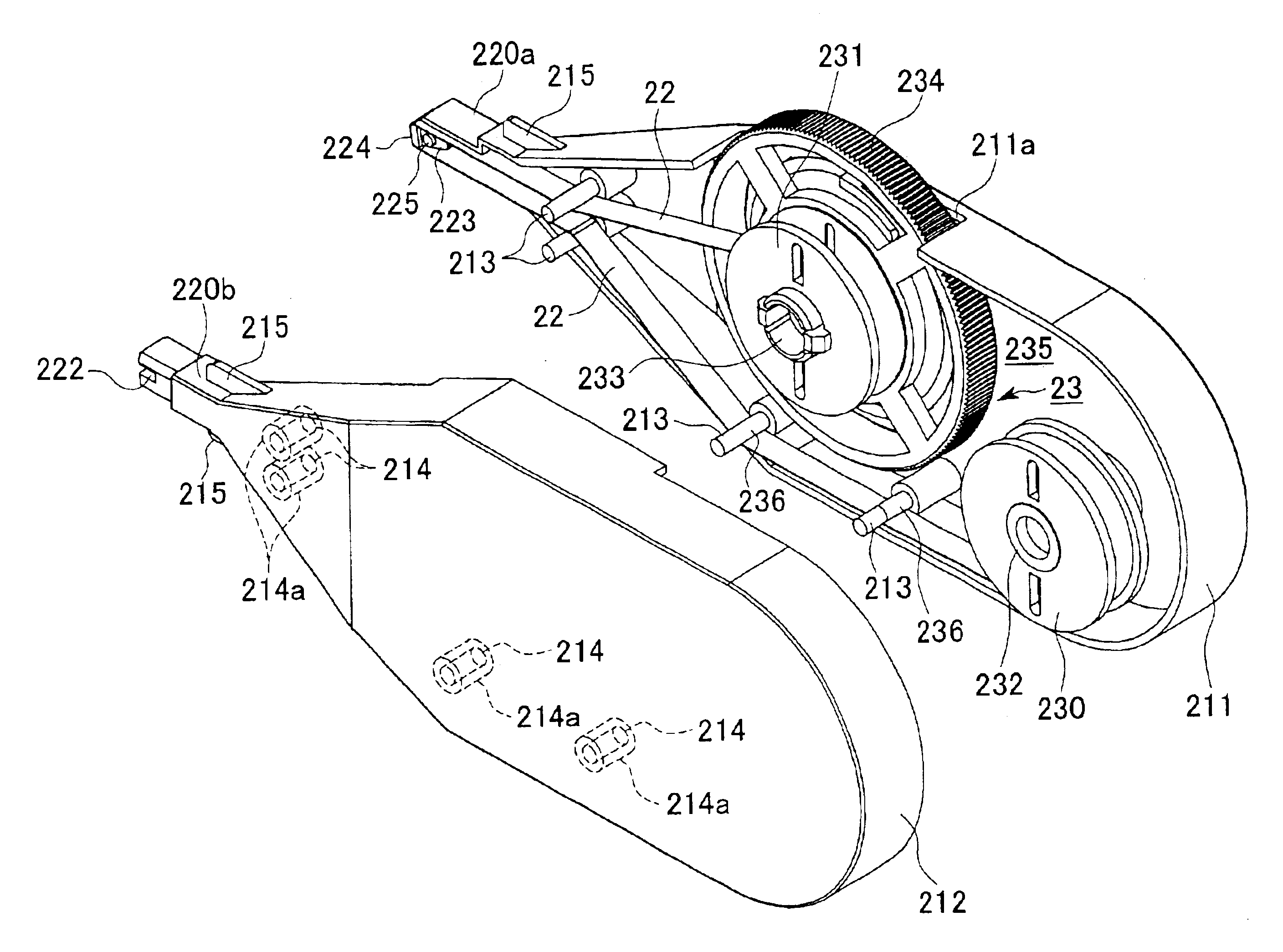
[0119]FIG. 12 is a perspective view showing a state in which the tool body of the cleaning tool is split into halves.

[0120]FIG. 13A is a schematic side view showing the above cleaning tool.

[0121]FIG. 13B is a side view showing a state in which the insertion portion of the cleaning tool is inserted into a connector housing while being positioned by a first insertion unit, and FIG. 13C is a side view showing a state in which the insertion portion of the cleaning tool is inserted into another connector housing while being positioned by a second insertion unit.

[0122]FIG. 14 is a perspective view...

third embodiment

[0176]Next, the present invention will be explained in detail below based on the

[0177]FIGS. 16A and 16B are respectively a perspective view and a side view showing an optical connector cleaning tool according to the third embodiment, and FIG. 17 is a perspective view showing a state in which the tool body of the cleaning tool is split into halves.

[0178]FIG. 18 is an exploded perspective view showing a state in which an insertion portion of the cleaning tool is going to be inserted into a connector insertion hole of a connector housing in which an optical connector is accommodated, FIG. 19 is a perspective view showing a state in which the insertion portion has been inserted into the connector insertion hole, and FIG. 20 is a cross-sectional view showing a state in which the insertion portion has been inserted into the connector insertion hole.

[0179]FIG. 21 is a partially enlarged cross-sectional view showing a tip portion of the cleaning tool. FIG. 22 is a front view showing a conne...


PUM


Abstract

An optical connector cleaning tool, which can easily and reliably clean a connecting end face of an optical connector while the optical connector is disposed in a connector housing, is disclosed. The optical connector cleaning tool comprises a tool body, and an insertion portion which is provided so as to project from the tool body, and which is adapted to be inserted into the connector housing, and the optical connector cleaning tool is adapted such that the cleaning element disposed at an end of the insertion portion projecting from the tool body is positioned and abutted against the connecting end face when the insertion portion is inserted into the connector housing. It is easy to insert the cleaning element into the connector housing and to abut the cleaning element against the connecting end face. Furthermore, it is easy to maintain the cleaning element in position abutting against the connecting end face when the cleaning element is moved for wiping the connecting end face.

Description

BACKGROUND OF THE INVENTION[0001]1. Field of the Invention[0002]This invention relates to an optical connector cleaning tool for cleaning a connecting end face of an optical connector disposed inside a connector housing.[0003]2. Background Art[0004]As is well known in the art, an optical connector, referred to as a “plug-adapter-plug connecting type optical connector”, is an optical connector in which optical connectors (plugs) are inserted into a connector housing as an adapter from both ends thereof so that the optical connectors are connected to each other inside the adapter.[0005]On the other hand, an optical connector, referred to as a “plug-receptacle connecting type optical connector”, is an optical connector in which one optical connector to be connected (such as a ferrule) is held inside a connector housing as a receptacle, and the other optical connector (a plug) is inserted into the receptacle so as to face the one optical connector and so as to be connected thereto.[0006...

Claims


Application Information

Patent Timeline
Patent Type & Authority Patents(United States)
IPC IPC(8): B08B11/00B08B1/00G02B6/38
CPCB08B1/008B08B11/00G02B6/3866G02B6/3807G02B6/3893
Inventor FUJIWARA, KUNIHIKOISHIKAWA, TAKAAKITANAKA, YUWA
Owner THE FUJIKURA CABLE WORKS LTD
Why Eureka
Try Eureka