
Transfer device

a transfer device and braking force technology, applied in the field of transfer devices, can solve the problems of loosened -shaped ribbons, unable to engage the rotation of feed shaft units failure of feed shaft units to rotate engagedly with the roll up shaft units, etc., to achieve stable handling of the transfer device, reduce braking force more slowly, and reduce the effect of braking for

Inactive Publication Date: 2005-06-14
GENERAL CO LTD
View PDF30 Cites 9 Cited by
  • Summary
  • Abstract
  • Description
  • Claims
  • Application Information

AI Technical Summary

Benefits of technology

"The present invention provides a transfer device that can maintain a constant tension of a band-shaped ribbon from the beginning to the end of operation through a mechanism that decreases the braking force applied to the feed drive gear. This is achieved by constructing the transfer device with a feed shaft and a roll up shaft, and a feed drive gear and a roll up drive gear that rotate while the band-shaped ribbon is being supplied. A spring is fitted between the inner periphery of the feed drive gear and the outer periphery of the feed shaft unit to apply a force in the axially expanding direction. A movable plate screw-retreats from the feed drive gear little by little in response to the rotation of the feed drive gear, which decreases the force of the spring. The transfer device can be constructed with a roll up speed-reduction gear and a feed speed-reduction gear to allow for a gradual decrease in the braking force. An intermediate speed-reduction gear can be added to further decrease the braking force and provide more stable manipulation."

Problems solved by technology

In the transfer device of this type, malfunction occurs if the tension of the band-shaped ribbon in the region between the feed shaft unit and the roll up shaft unit (hereinafter referred to as “tension”) is too high or too low.
More specifically, when the tension is too low, the band-shaped ribbon may be loosened and the feed shaft unit may fail to rotate engagedly with the roll up shaft unit.
This method, however, has a following drawback, as the braking force is kept constant from the beginning till the end of operation.
At the end of operation, however, the tension of the band-shaped ribbon is higher compared with the standard tension during the normal traveling at the start, since the roll diameter of the feed shaft unit becomes smaller at the end than the roll diameter of the feed shaft unit at the start, which makes the traveling to be heavy.
Such a tension fluctuation of the band-shaped ribbon from the beginning till the end of operation deteriorates the maneuverability of the transfer device for the user, making handling of the device to be difficult.
However, according to the structure of Japanese laid-open patent publication No. 9-71097 described as above in which the tension of the band-shaped ribbon can be varied, the user is required to manipulate the variable button appropriately, which requirement forced on the user deteriorates the convenient feature of the transfer device.
Moreover, since the user is not particularly conscious of the relationship between the amount of use and the tension of the band-shaped ribbon, it is extremely difficult to actually keep the tension of the band-shaped ribbon constant.

Method used


Image

  • Transfer device
  • Transfer device
  • Transfer device

Examples


first embodiment

[0031](First Embodiment)

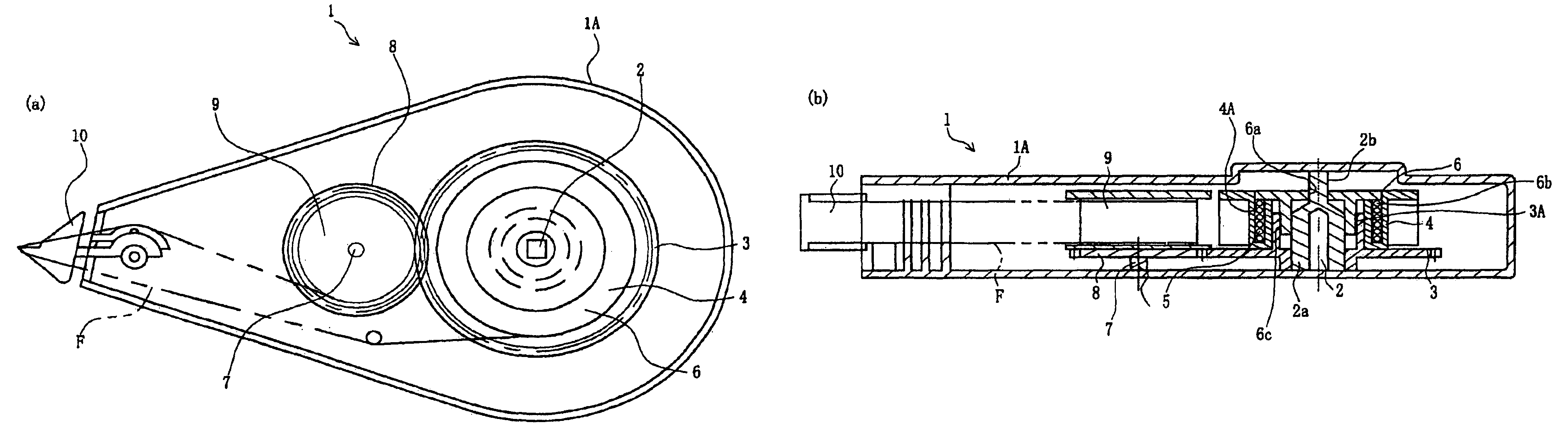
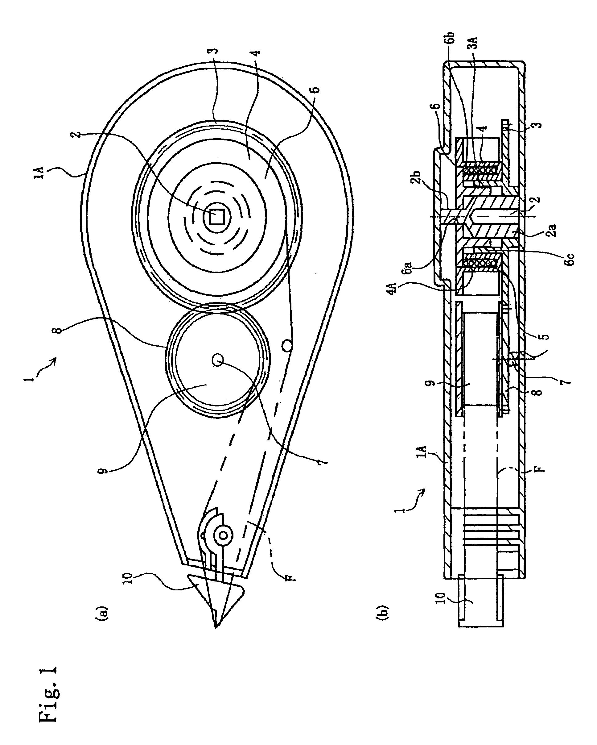
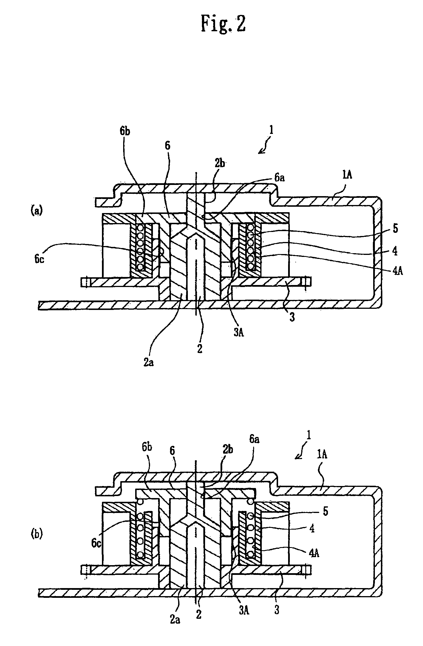
[0032]As shown in FIGS. 1 and 2, a transfer device 1 has the following structure of the present invention. A feed shaft 2 is provided within a casing 1A. The feed shaft 2 has a cylindrical shape in the lower portion viewed in FIG. 1(b) (hereinafter referred to as “feed shaft lower portion 2a”) and has a solid prism shape in the upper portion viewed in that figure (hereinafter referred to as “feed shaft upper portion 2b”).

[0033]A feed drive gear 3 is supported on the feed shaft lower portion 2a. The axial lower portion of the feed drive gear 3 contacts with the feed shaft lower portion 2a. The upper portion of the feed drive gear 3 axially extends, which extending portion is positioned away from the outer periphery of the feed shaft lower portion 2a. Further, a screw-shaped advance / retreat portion 3A (the area shown by a bold line is screw-shaped in the figure) is formed on the inner periphery of the above extending portion of the feed drive gear 3 facing to t...

second embodiment

[0046](Second Embodiment)

[0047]As shown in FIGS. 3 and 4, a transfer device 11 has a following structure in accordance with the present invention. Explained herein are only the different points between the structure of the transfer device 11 and that of the transfer device 1 of the first embodiment shown in FIGS. 1 and 2. A feed speed-reduction gear 12 is provided. The lower inner periphery of the feed speed-reduction gear 12 contacts the feed shaft lower portion 2a. The upper portion of the feed speed reduction gear 12 projects in the axial direction. An advance / retreat portion 12A (shown by a bold line) is formed on the outer periphery of the projecting portion of the feed speed-reduction gear 12.

[0048]In the transfer device 11, the screw portion 6c is formed on the inner periphery of the movable plate 6 so as to be screw-engaged with the advance / retreat portion 12A of the above feed speed-reduction gear 12. The feed drive gear 3 is inserted through the outer periphery of the feed...

third embodiment

[0055](Third Embodiment)

[0056]As illustrated in FIGS. 5 and 6, transfer devices 21 and 31 have the following structures according to the present invention. Explained first is the structure of the transfer device 21 only at the points different from those of the transfer device 11 of the second embodiment as shown in FIGS. 3 and 4. In the transfer device 21, the feed speed-reduction gear 12 and the roll up speed-reduction gear 13 does not engage with each other, between which gears an intermediate speed-reduction gear 14 is interposed.

[0057]The intermediate speed-reduction gear 14 consists of an upper member 14a having a smaller diameter and mating with the feed speed-reduction gear 12, and a lower member 14b having a larger diameter and mating with the roll up speed-reduction gear 13. The intermediate speed-reduction gear 14 integrally connects the upper member 14a and the lower member 14b. The feed speed-reduction gear 12 and the roll up speed-reduction gear 13 both have appropriat...


PUM

PropertyMeasurementUnit
diameteraaaaaaaaaa
diameteraaaaaaaaaa
spring forceaaaaaaaaaa

Abstract

Provided is a transfer device capable of maintaining a constant tension of band-shaped ribbon from the start till the end of operation requiring no action by a user. While band-shaped ribbon (F) is being supplied, a feed shaft unit (4) and a feed drive gear (3) rotate. In accordance with their rotations, a movable plate (6) screw-retreats so that the interval between the movable plate (6) and the surface of the feed drive gear (3) is increased in the axial direction. Consequently, the force of a coil spring (5) is reduced and the braking force (a force to press the surface of the feed drive gear (3) to stop its rotation) is gradually decreased.

Description

TECHNICAL FIELD[0001]The present invention relates to a transfer device maintaining a constant tension of band-shaped ribbon from the beginning till the end of operation.TECHNICAL BACKGROUND[0002]Recently, a transfer device for transferring a coating film onto a transfer-receiving object such as paper has been widely used because of its advantageous feature of easy handling for supplying an adequate amount as a replacement for touch-up liquid and liquid paste. A transfer device applying a white correction film for touch-up makes a correction by transferring the correction film onto a correction point of a transfer-receiving object. A transfer device employing an adhesive film for adhesively connects the transfer-receiving object and an attachment substance fixes the attachment substance to the adhesive film transferred onto the transfer-receiving object.[0003]Both types of the above-described transfer devices have similar structures except for the coating film used which is adhesive...

Claims


Application Information

Patent Timeline
Patent Type & Authority Patents(United States)
IPC IPC(8): B65H37/00
CPCB65H37/007Y10T156/1795Y10T156/18
Inventor TOMINAGA, MITSUHIRO
Owner GENERAL CO LTD
Learn More