Process for molding on a substrate

a technology of injection molding and substrate, which is applied in the direction of ceramic shaping apparatus, other domestic objects, manufacturing tools, etc., can solve the problems of small gaps between the mating faces, degree of mismatch between the faces, and inability to produce foam rim parts

Inactive Publication Date: 2005-06-14
CASCADE ENG
View PDF8 Cites 9 Cited by
  • Summary
  • Abstract
  • Description
  • Claims
  • Application Information

AI Technical Summary

Benefits of technology

[0009]The process of the invention allows a substantially flash free molded component to be formed directly on a substrate. The process eliminates t

Problems solved by technology

Unfortunately, there is usually some degree of mismatch between the faces.
This mismatch of the mold segments results in the formation of small gaps between the mating faces at the parting line.
Heretofore, it has not been possible to produce a foam RIM part without unwanted thin protrusions (flash) at the edges of the part which were located at the parting line of the mold segments.
However, these apparatuses and processes have achieved very limited success.
Mechanical flash removal apparatuses have generally failed to consistently remove all of the flash material from a RIM part and/or have removed surface material from the RIM part resulting in destruction of texturing or other surface features of the

Method used


Image

  • Process for molding on a substrate
  • Process for molding on a substrate

Examples


Embodiment Construction

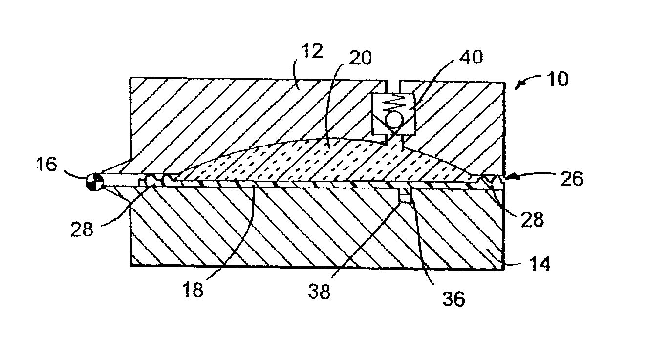
[0016]In FIG. 1, there is shown a cross-sectional view of a mold 10 comprising a mold segment 12, and a mold segment 14. Mold segments 12 and 14 are hinged together with a precision open / close mechanism 16. When the mold 10 is closed, as shown in FIG. 1, mold segment 12 and mold segment 14 together define a mold cavity in which an injection molded thermoplastic substrate 18 is disposed, and in which a mixture of liquid reactants is injected and reacted to form a molded component 20 which conforms with the remaining shape of the mold cavity that is not occupied by substrate 18. Mold segments 12 and 14 have complementary shaped faces 22 and 24 that mate with each other at a parting line 26.

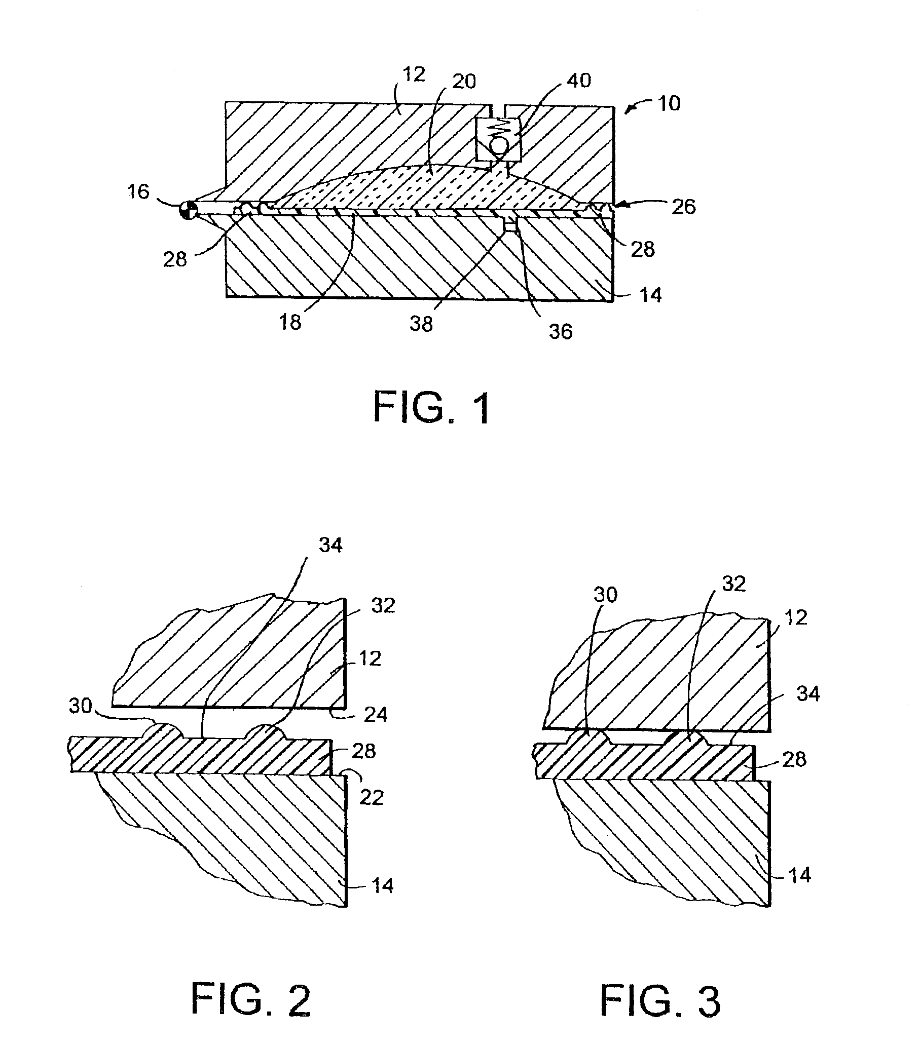
[0017]Substrate 18 has a contoured surface which conforms with mold cavity defining surfaces of mold segment 12. In the illustrated embodiment, substrate 18 is a substantially flat panel or sheet, and mold segment 12 has a substantially flat surface conforming with the shape of substrate 18. Substra...


PUM

PropertyMeasurementUnit
Moldableaaaaaaaaaa
Thermoplasticityaaaaaaaaaa

Abstract

A process of molding a component on a substrate utilizes a substrate having a peripheral flange that projects into a parting line between mold segments defining a mold cavity, wherein the flange has a projecting, continuous circuitous ridge that forms a seal between the substrate and an upper mold segment. The process allows a substantially flash free molded component to be formed directly on a substrate, thus eliminating the need for a separate flash removal step.

Description

FIELD OF THE INVENTION[0001]This invention relates to injection molding processes, and more particularly to molding on a substrate.BACKGROUND OF THE INVENTION[0002]Reaction injection molding (RIM) is a process for molding polymeric parts by injecting low molecular weight, reactive, low viscosity liquids at high pressure into a mixing chamber and then into a mold cavity. The liquid reactants polymerize in the mold to form a molded article. Molds used for reaction injection molding, like many molds, comprise at least two segments, which in a mold-closed position, come together to define a mold cavity into which the reactants are injected. The mold segments have complimentary shaped faces which come together when the mold is closed to define a parting line. Unfortunately, there is usually some degree of mismatch between the faces. This mismatch of the mold segments results in the formation of small gaps between the mating faces at the parting line. Such gaps allow liquid mixture inject...

Claims


Application Information

Patent Timeline
IPC IPC(8): B29C45/14B29C67/24
CPCB29C45/14065B29C45/14418B29C45/0025B29C67/246B29L2031/3005B29C2045/14131B29C2045/14934B29K2105/04B29C2045/0483
Inventor JUNKER, CHRISTIANANDERSON, MICHAEL J.
Owner CASCADE ENG
Why Eureka
Try Eureka