
Burst switching in a high capacity network

a high-capacity network and burst switching technology, applied in data switching networks, frequency-division multiplexes, instruments, etc., can solve the problems of low network utilization, burst may be lost, and the source node is unknown to the core node, so as to achieve efficient utilization of network resources.

Inactive Publication Date: 2005-06-14
RPX CLEARINGHOUSE
View PDF16 Cites 41 Cited by
  • Summary
  • Abstract
  • Description
  • Claims
  • Application Information

AI Technical Summary

Benefits of technology

[0006]At a controller of a space switch, a novel burst scheduling technique allows efficient utilization of network resources. Burst transfer requests are received at the space switch controller and pipelined such that the controller may determine a schedule for allowing the bursts, represented by the burst transfer requests, access to the space switch. According to the schedule, scheduling information is distributed to the sources of the burst transfer requests and to a controller of the space switch.
[0007]Advantageously, the novel burst scheduling technique allows for utilization of network resources that is more efficient than typical burst switching techniques, especially when the novel burst scheduling technique is used in combination with known time locking methods. The novel burst scheduling technique enables the application of burst switching to wide coverage networks. Instead of handling burst requests one-by-one, burst requests are pipelined and the handling of the bursts is scheduled over a long future period.

Problems solved by technology

Core nodes without buffers are desirable because: it may not be possible to provide buffers without an expensive optical-electrical conversion at input and electrical-optical conversion at output of an optical space switch; and the core node may be distant from the source and sink (edge) nodes, therefore requiring remote buffer management in an edge-controlled network.
In the first scheme, a burst may arrive at a core node before the space switch is properly configured and, if the core node does not include a buffer, the burst may be lost.
Furthermore, until the source node fails to receive an acknowledgement of receipt of the burst from the burst destination, the fact that the burst has been lost at the core node is unknown to the source node.
In the second scheme, the time delay involved in sending a burst transfer request and receiving an acceptance before sending a burst may be unacceptably high, leading to low network utilization.

Method used


Image

  • Burst switching in a high capacity network
  • Burst switching in a high capacity network
  • Burst switching in a high capacity network

Examples


Embodiment Construction

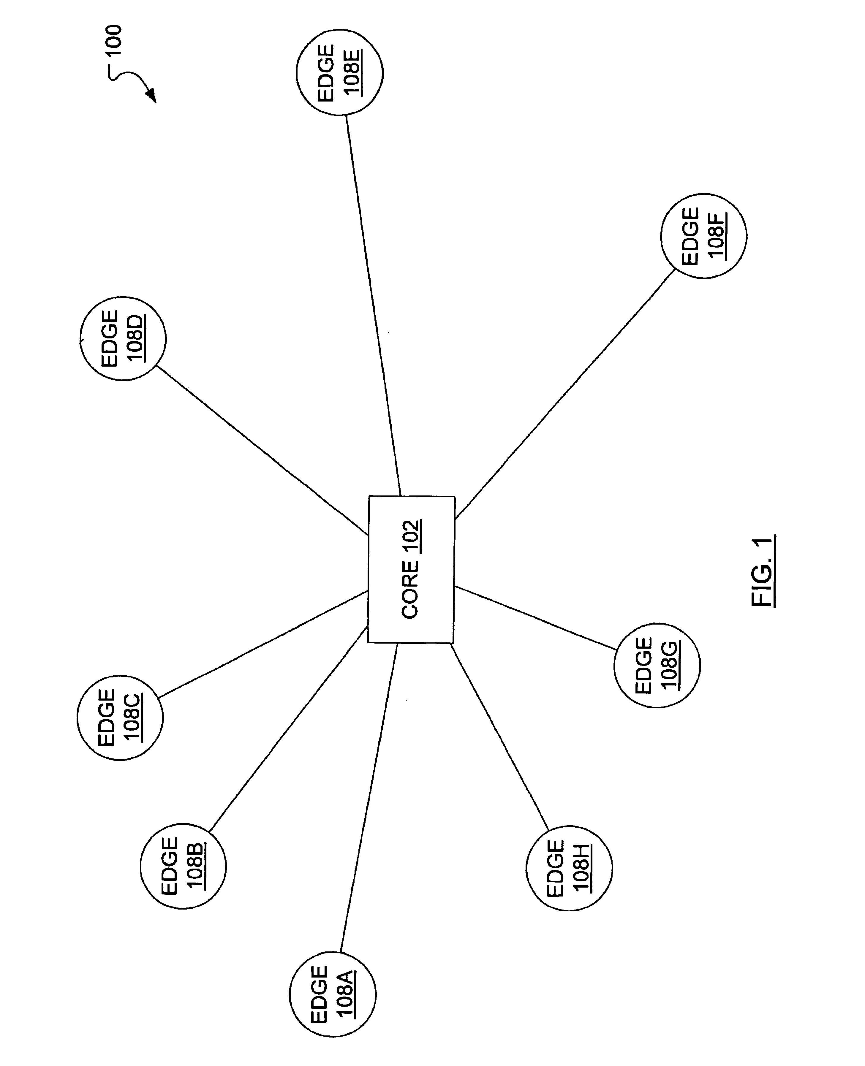
[0038]FIG. 1 illustrates a rudimentary “hub and spoke” data network 100 wherein a number of edge nodes 108A, 108B, 108C, 108D, 108E, 108F, 108G, 108H (referred to individually or collectively as 108) connect to each other via a core node 102. An edge node 108 includes a source node that supports traffic sources and a sink node that supports traffic sinks. Traffic sources and traffic sinks (not shown) are usually paired and each source node is usually integrated with a sink node with which it shares memory and control.

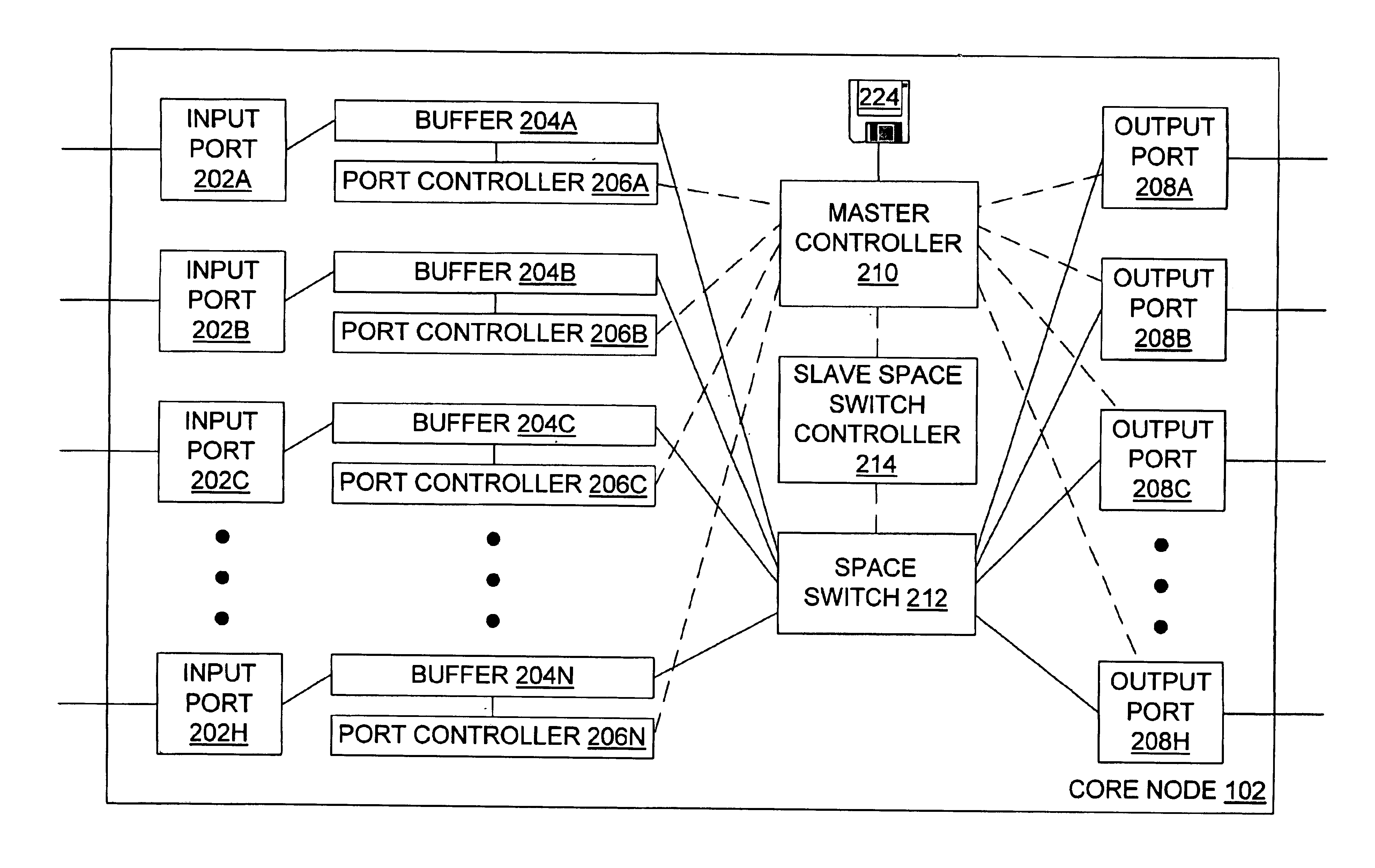
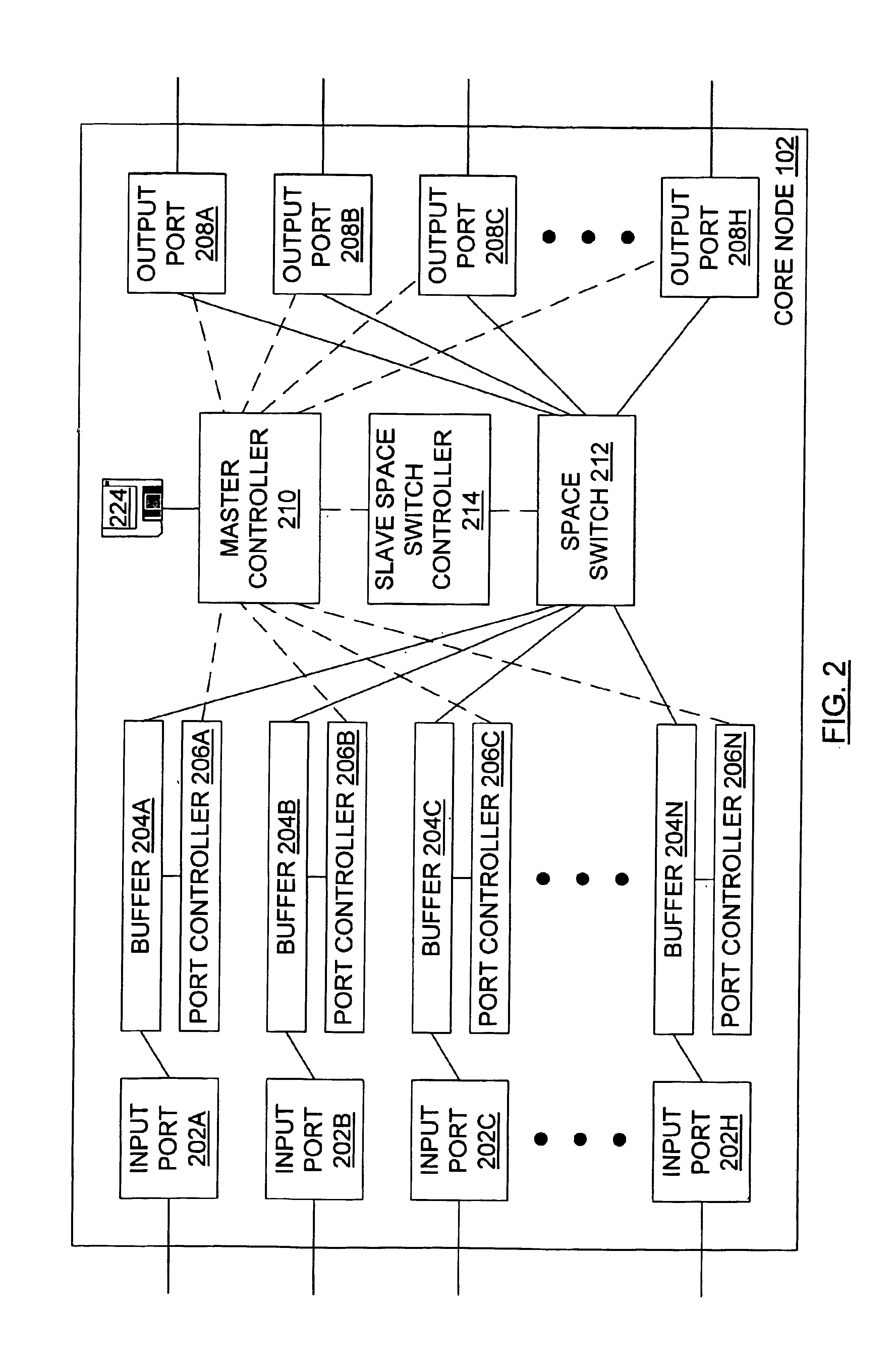
[0039]The core node 102 may be considered in greater detail in view of FIG. 2, which illustrates an electronic core node. The core node 102 includes N input ports 202A, 202B, 202C, . . . , 202N (referred to individually or collectively as 202) for receiving data from the edge nodes 108 of FIG. 1. Each of the N input ports 202 is connected to a corresponding buffer 204A, 204B, 204C, . . . , 204N (referred to individually or collectively as 204) that is connected to a cor...


PUM


Abstract

At a master controller of a space switch in a node in a data network, a request is received from a source node that requests a connection to be established through the space switch. This request is compared to other such requests so that a schedule may be established for access to the space switch. The schedule is then sent to the source nodes as well as to a slave controller of the space switch. The source nodes send data bursts which are received at the space switch during a short guard time between successive reconfigurations of the space switch. Data bursts are received at the space switch at a precisely determined instant of time that ensures that the space switch has already reconfigured to provide requested paths for the individual bursts. The scheduling is pipelined and performed in a manner that attempts to reduce mismatch intervals of the occupancy states of input and output ports of the space switch. The method thus allows efficient utilization of the data network resources while ensuring virtually no data loss.

Description

GOVERNMENT LICENSE RIGHTS[0001]This invention was made with Government support under Technology Investment Agreement F30602-98-2-0194 awarded by the Air Force. The Government has certain rights in the invention.FIELD OF THE INVENTION[0002]The present invention relates to data communication networks and, in particular, to burst switching in a high capacity network.BACKGROUND OF THE INVENTION[0003]In burst switching, a source node sends a burst transfer request to a core node to indicate that a burst of data is coming, the size of the burst and the destination of the burst. Responsive to this burst transfer request, the core node configures a space switch to connect a link on which the burst will be received to a link to the requested burst destination. In a first scheme, the burst follows the burst transfer request after a predetermined time period (a scheduling time) and it is expected that, when the burst arrives at the core node, the space switch will have been properly configured...

Claims


Application Information

Patent Timeline
IPC IPC(8): H04Q11/06H04Q3/00H04Q11/00
CPCH04Q3/0091H04Q11/0066H04Q11/06H04Q2011/0039H04Q2011/0064H04Q2213/13166H04Q2213/1305H04Q2213/13103H04Q2213/13106H04Q2213/13164H04Q2011/0088
Inventor BESHAI, MAGED E.VICKERS, RICHARD
Owner RPX CLEARINGHOUSE
Learn More