Method of monitoring packet communications traffic

a packet communication and traffic monitoring technology, applied in the field of packet communication traffic monitoring, can solve the problems of inability to send all at the same time, inability to monitor packet communication traffic, and inability to tolerate buffering of delay-sensitive traffic such as voice, and achieve the effect of accurate determination of peak cell ra

Inactive Publication Date: 2005-06-14
RPX CLEARINGHOUSE
View PDF9 Cites 26 Cited by
  • Summary
  • Abstract
  • Description
  • Claims
  • Application Information

AI Technical Summary

Benefits of technology

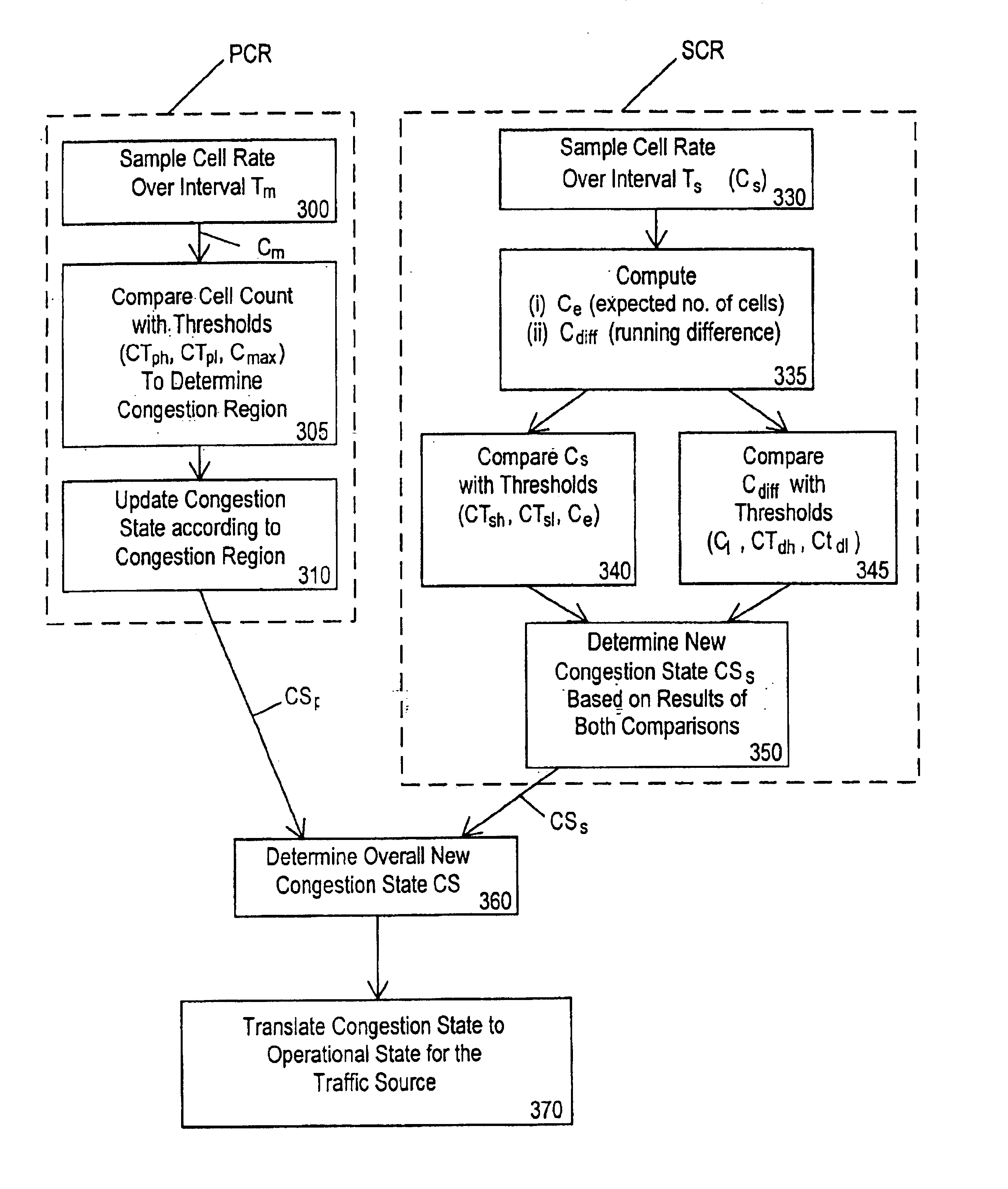
[0013]Monitoring based on cell counts taken over a period of time rather than performing a congestion algorithm on a per cell basis means that the need for specialised hardware can be avoided as significantly less processing is required. The congestion function can be performed in software.
[0017]Preferably the new congestion state is a function of the old congestion state and the measured parameters. This prevents large swings in the operational state of the source.
[0023]Preferably the second time interval is a shorter interval than the first interval. This allows a more accurate determination of peak cell rate. Advantageously the second time interval is in the range 50-500 ms, and preferably it is around 100 ms.

Problems solved by technology

Variable bit rate (VBR) traffic poses particular problems for traffic management as the bit rate of the traffic varies during a call.
Clearly, if the offered traffic exceeds the available capacity, it cannot all be sent at the same time.
However, delay-sensitive traffic such as voice cannot tolerate buffering and therefore cannot be treated in this way.
This makes it difficult to predict the actual sustained cell rate (average bandwidth) for a voice trunk using a fixed coding scheme because the ratio of talk to silence is not deterministic.

Method used


Image

  • Method of monitoring packet communications traffic
  • Method of monitoring packet communications traffic
  • Method of monitoring packet communications traffic

Examples


example 1

[0176]Min_Voice_Rate=24 kb / s[0177]Max_Voice_Rate=64 kb / s[0178]Modem_Rate=64 kb / s[0179]Silence Suppression=on congestion

[0180]

VoicebandVoicebandDataVoiceDataOperationalDigital DataCongestionOperationalOperationalStateOperationalStateStateState(Violating)StateCS0OS0VBD_OS0VBD_OS0DOS0CS1OS1VBD_OS0VBD_OS0DOS0CS2OS3VBD_OS0VBD_OS0DOS0CS3OS5VBD_OS0VBD_OS0DOS0CS4OS5VBD_OS0VBD_OS2DOS1

example 2

[0181]Min_Voice_Rate=16 kb / s[0182]Max_Voice_Rate=32 kb / s[0183]Modem_Rate=64 kb / s[0184]Silence Suppression=on

[0185]

VoicebandVoicebandDataVoiceDataOperationalDigital DataCongestionOperationalOperationalStateOperationalStateStateState(Violating)StateCS0OS3VBD_OS0VBD_OS0DOS0CS1OS5VBD_OS0VBD_OS0DOS0CS2OS7VBD_OS0VBD_OS0DOS0CS3OS7VBD_OS0VBD_OS3DOS1

example 3

[0186]Min_Voice_Rate=16 kb / s[0187]Max_Voice_Rate=32 kb / s[0188]Modem_Rate=32 kb / s[0189]Silence Suppression=on congestion

[0190]

VoicebandVoicebandDataVoiceDataOperationalDigital DataCongestionOperationalOperationalStateOperationalStateStateState(Violating)StateCS0OS2VBD_OS1VBD_OS1DOS0CS1OS3VBD_OS1VBD_OS1DOS0CS2OS5VBD_OS1VBD_OS1DOS0CS3OS7VBD_OS1VBD_OS1DOS0CS4OS7VBD_OS1VBD_OS3DOS1


PUM


Abstract

A flow of packet or cell-based communications traffic is monitored by: setting a first time interval over which measurements are to be made; counting number of packets flowing during that time interval and using the count to derive parameters which are indicative of the traffic meeting a sustained cell rate (SCR) requirement. Use of this cell counting method rather than a per-cell computation of a generic cell rate algorithm (GCRA) reduces computation requirements in monitoring traffic. Preferably the cell count is used to derive a running difference between the counted number of packets and an expected number of packets.

Description

TECHNICAL FIELD[0001]This invention relates to a method and apparatus for monitoring rate of flow of packet or cell-based communications traffic. It is particularly useful in policing or managing the traffic. The invention is particularly suited to packet-based communications systems such as Asynchronous Transfer Mode (ATM) systems which carry variable bit rate traffic.BACKGROUND OF THE INVENTION[0002]Communications systems typically have some form of congestion management function to allocate the resources, such as bandwidth on a communications link, to users in a way that prevents the system from becoming congested. Typically some form of connection admission control (CAC) responds to new call requests and admits or refuses calls.[0003]Integrated communications systems are now being developed which can carry a variety of types of traffic, such as voice, data and video. Traffic can be a mix of constant bit rate and variable bit rate traffic. Variable bit rate (VBR) traffic poses pa...

Claims


Application Information

Patent Timeline
Patent Type & Authority Patents(United States)
IPC IPC(8): H04L12/26H04L12/24H04L12/54H04L12/70
CPCH04L12/2602H04L12/5601H04L43/00H04L12/2692H04L43/022H04L43/0829H04L2012/568H04L43/087H04L43/0882H04L43/0894H04L43/16H04L2012/5635H04L2012/5636H04L43/0852
Inventor GVOZDANOVIC, RADE
Owner RPX CLEARINGHOUSE
Why Eureka
Try Eureka