Moving image encoding apparatus

a moving image and encoding technology, applied in the direction of color television with bandwidth reduction, signal generator with optical-mechanical scanning, television systems, etc., can solve the problems of data error diffused, residual deterioration in image quality gradually increasing, etc., to prevent data error diffuse, accurate determine the necessity of refresh, and prevent deterioration in image quality

Inactive Publication Date: 2005-06-14
KK TOSHIBA
View PDF15 Cites 17 Cited by
  • Summary
  • Abstract
  • Description
  • Claims
  • Application Information

AI Technical Summary

Benefits of technology

[0018]The present invention has been made to solve these problems, and has as its object to provide an moving image encoding apparatus which can accurately determine the necessity of refresh by intra-encoding in the inter-frame encoding mode, and prevent from diffusing a data error, even if it occurs, by motion compensation prediction processing.
[0019]It is an object of the present invention, in particular, to prevent a deterioration in image quality from remaining and a data error from diffusing when refresh is cyclically performed. It is another object of the present invention to prevent unrefreshed macroblocks from remaining and remaining blocks from increasing in number when aperiodical refresh is performed in units of macroblocks. It is still another object of the present invention to properly determine whether a macroblock in one frame is a refresh target or not.
[0031]With this processing, whether refresh is required for each macroblock in one frame can be properly determined. Even if the technique of cyclically performing refresh by intra-encoding is used, a macroblock that requires refresh is refreshed when it is required upon switching to the intra-encoding mode without waiting for the next refresh cycle. This makes it possible to prevent a deterioration in image quality due to a data error from remaining and a data error from diffusing.
[0033]According to the arrangement of (5), an error rate in a transmission path is detected, and both or one of the update reference value for updating the parameter value and the criterion value for the execution of the intra-encoding mode is changed in accordance with the detected error rate, thereby setting a condition for the execution of refresh operation in the intra-encoding mode in accordance with the error rate in the transmission path. This can prevent a deterioration in image quality from remaining on the moving image decoding apparatus side.
[0035]According to the arrangement of (6), both or one of the update reference value for updating the parameter value and the criterion value for the execution of intra-encoding is changed by using the encoded data storage means (26) for keeping the transmission rate constant in accordance with the amount of encoded data stored in the encoded data storage means (26), thereby setting a condition for the execution of refresh operation in the intra-encoding mode in accordance with the amount of encoded transmission data. This can prevent a deterioration-in image quality from remaining on the moving image decoding apparatus side.

Problems solved by technology

First of all, as in the first scheme defined in ITU-T H.263 described above, the following problem arises in the method of cyclically performing refresh. In this method, for a macroblock for which intra-encoding has been performed in a given frame, refresh is not performed until the next intra-encoding period. For this reason, if the data of a given macroblock is destroyed immediately after refresh is performed once by intra-encoding in one frame, a deterioration in image quality remains until the next refresh is performed, and the data error is diffused to neighboring macroblocks by motion compensation prediction processing.
As in the second scheme defined in MPEG-4 described above, the following problem arises in the method of performing refresh in units of macroblocks by aperiodical intra-encoding.
As a consequence, a residual deterioration in image quality gradually increases.
Even in this case, if the number of DCT coefficients is small upon discrete cosine transform, the amount of encoded data used for one macroblock decreases, and the probability of mixing of an error decreases.
Therefore, correct determination cannot be made by the technique of performing determination on the basis of only the pixel difference value in one frame.

Method used


Image

  • Moving image encoding apparatus
  • Moving image encoding apparatus
  • Moving image encoding apparatus

Examples


first embodiment

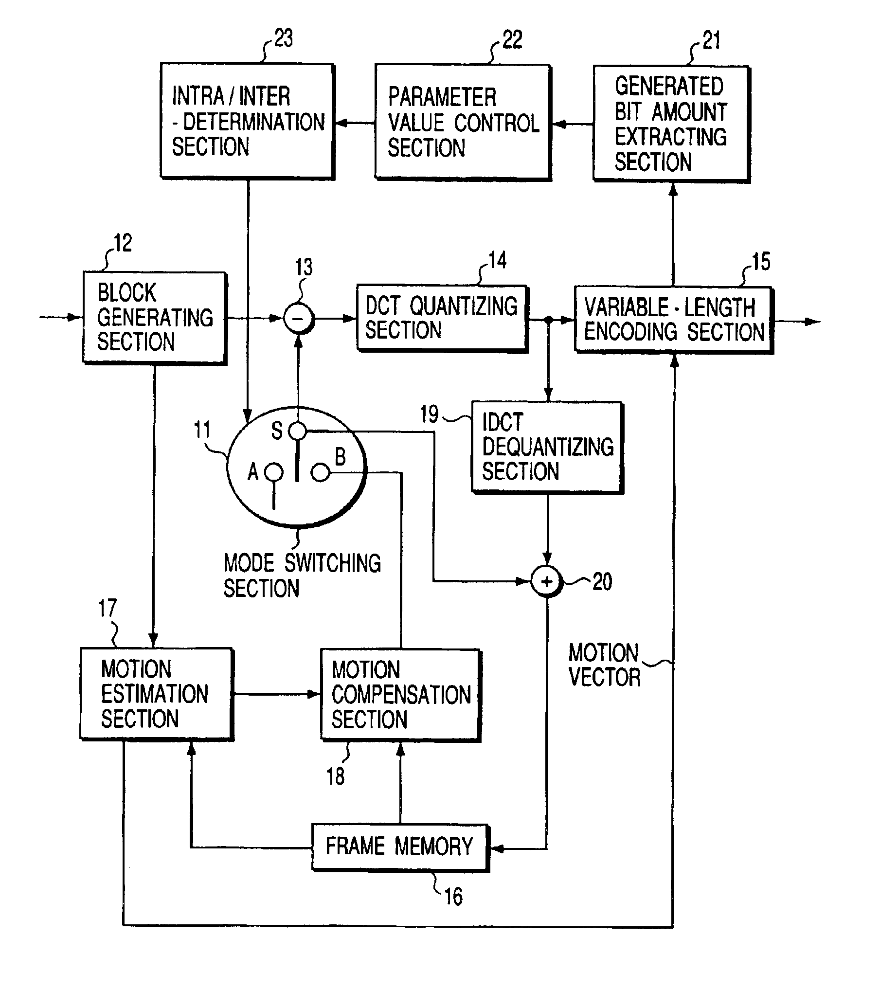
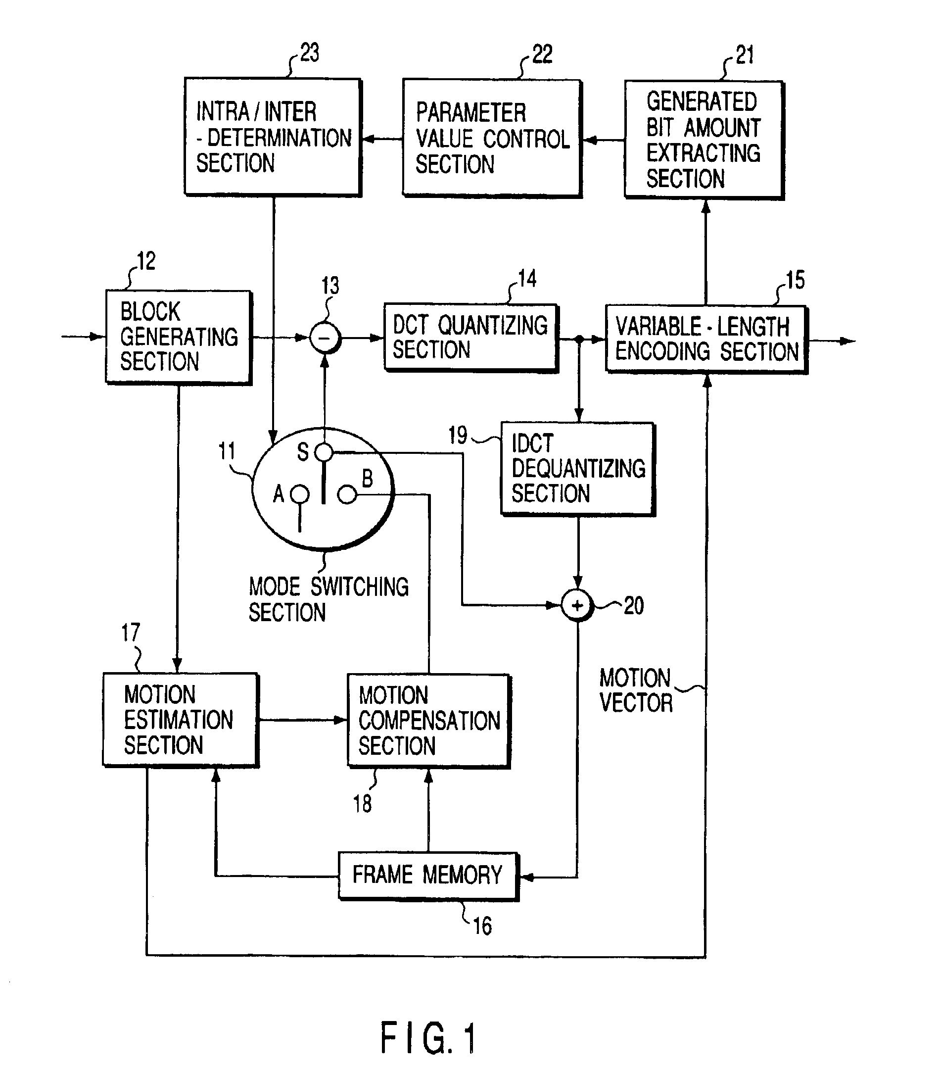
[0048]FIG. 1 is a block diagram showing the arrangement of a moving image encoding apparatus according to the first embodiment of the present invention.

[0049]A moving image encoding apparatus according to the first embodiment is characterized in that the number of encoded bits generated by variable-length-encoding data obtained by DCT coefficient quantization are monitored in units of macroblocks, thereby choosing between intra-encoding and inter-encoding for macroblocks to be processed in the next frame. More specifically, if the amount of encoded data generated by variable length encoding is large, it is determined that a large variation is occurring in the input image. In accordance with this determination, the number of bits of encoded data is counted. More specifically, if the amount of encoded data generated by variable length encoding is large, it is determined that a large variation is occurring in the input image. In accordance with this determination, the number of bits of...

second embodiment

[0079]FIG. 4 is a block diagram showing the arrangement of a moving image encoding apparatus according to the second embodiment of the present invention.

[0080]The moving image encoding apparatus of the second embodiment is characterized in that whether to intra-encode macroblocks in the next frame or inter-encode them is selected by monitoring whether a non-zero coefficient amount obtained by a DCT-quantizing section 14 is large or small in units of macroblocks. If the number of non-zero coefficients of the DCT coefficients obtained by DCT computation is large, it can be determined that a large variation is occurring in the input image. By using this, non-zero coefficients are counted, and it is determined in accordance with this count value whether to perform refresh operation or not.

[0081]The moving image encoding apparatus shown in FIG. 4 is comprised of a mode switching section 11, a block generating section 12, a subtracter 13, the DCT-quantizing section 14, a variable-length e...

third embodiment

[0091]FIG. 6 is a block diagram showing the arrangement of a moving image encoding apparatus according to the third embodiment of the present invention.

[0092]The moving image encoding apparatus according to the third embodiment is characterized in that both or one of an update condition for a parameter value T(n) and a criterion for the selection of intra / inter-encoding is updated in accordance with an error rate in a transmission path.

[0093]Referring to FIG. 6, the moving image encoding apparatus is comprised of a mode switching section 11, block generating section 12, subtracter 13, DCT-quantizing section 14, variable-length encoding section 15, frame memory 16, motion estimation section 17, motion compensation section 18, IDCT-dequantizing section 19, adder 20, parameter value control section 22, intra / inter determination section 23, total coefficient count extracting section 24, and error rate detecting section 25. The functional blocks denoted by the same reference numerals as ...


PUM


Abstract

In a moving image encoding apparatus of this invention, a generated bit amount extracting section (21) counts generated bits of variable-length-encoded data in units of macroblocks, and a reference generated bit count is set in a parameter value control section (22) as an update condition for a parameter value in each block. The boundary value of the parameter value is set in an intra / inter determination section (23) as a criterion for selection of the intra-encoding mode. In the inter-frame encoding mode, the parameter value control section (22) updates the parameter value of a block in which the generated bit count value of encoded data obtained by the generated bit amount extracting section (21) exceeds a reference value. The intra / inter determination section (23) determines that the influence of a data error is large in a block in which the parameter value is continuously updated and exceeds the boundary value, and switches the current mode to the intra-encoding mode to perform refresh operation.

Description

TECHNICAL FIELD[0001]The present invention relates to a moving image encoding apparatus for compressing and encoding a video signal (to be referred to as a moving image signal hereinafter) of a moving image with high efficiency.BACKGROUND ART[0002]A conventional moving image encoding apparatus is designed to compress and encode a moving image signal with high efficiency by using the statistical characteristics of a moving image signal, i.e., correlations between intraframe pixels and between interframe pixels, thereby realizing a great reduction in information amount.[0003]As basic schemes of compressing and encoding moving image signals, a predictive encoding scheme and transformational encoding scheme are available. The predictive encoding scheme uses correlations in time domains. The transformational encoding scheme uses correlations in spatial domains. As a predictive encoding scheme, a motion compensation predictive scheme of encoding a difference signal between an original ima...

Claims


Application Information

Patent Timeline
Patent Type & Authority Patents(United States)
IPC IPC(8): H04L1/00H04N7/26H04N7/50H04N19/50H04N19/102H04N19/107H04N19/146H04N19/15H04N19/166H04N19/176H04N19/196H04N19/423H04N19/503H04N19/60H04N19/61H04N19/625H04N19/65H04N19/85H04N19/91
CPCH04L1/0014H04N19/105H04N19/176H04N19/172H04N19/149H04N19/192H04N19/61H04N19/107H04N19/152H04N19/166H04N19/15
Inventor KAWAKATSU, HIROKAZUASANO, ATSUSHI
Owner KK TOSHIBA
Why Eureka
Try Eureka