Image recognition/reproduction method and apparatus

a technology of image recognition and reproduction method, applied in the field of image recognition/reproduction method and apparatus, can solve the problems of high computation cost, difficult to execute computations perfectly in automatic fashion, increase in computation cost, etc., and achieve the effect of short processing time and low computation cos

Inactive Publication Date: 2005-06-14
CANON KK
View PDF26 Cites 167 Cited by
  • Summary
  • Abstract
  • Description
  • Claims
  • Application Information

AI Technical Summary

Benefits of technology

[0013]Accordingly, an object of the present invention is to provide a pattern recognition method and apparatus in which recognition is performed based upon a limited number of feature elements and information relating to the relative disposition of the feature elements in space.
[0014]Another object of the present invention is to provide an image generating method and apparatus in which images are generated at low computation cost and in a short processing time without use of a detailed three-dimensional shape model.

Problems solved by technology

A problem that arises is an increase in cost of computations.
Such area partitioning and recognition of object patterns are two sides of the same thing and it is very difficult to execute them perfectly in automatic fashion.
As a result, computation costs are high and processing requires an extended period of time.

Method used


Image

  • Image recognition/reproduction method and apparatus
  • Image recognition/reproduction method and apparatus
  • Image recognition/reproduction method and apparatus

Examples


first embodiment

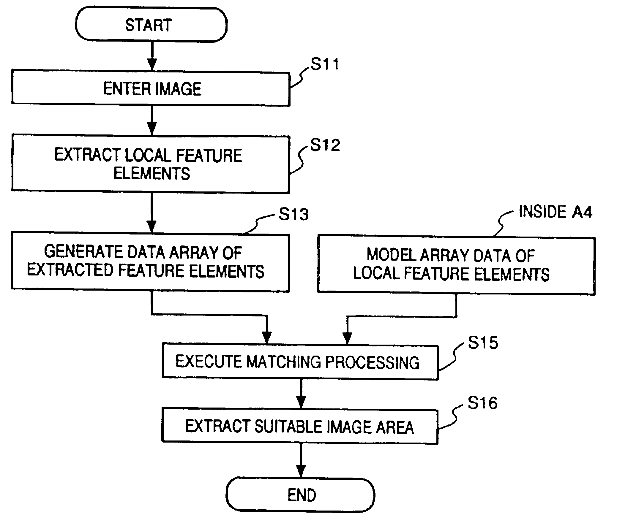
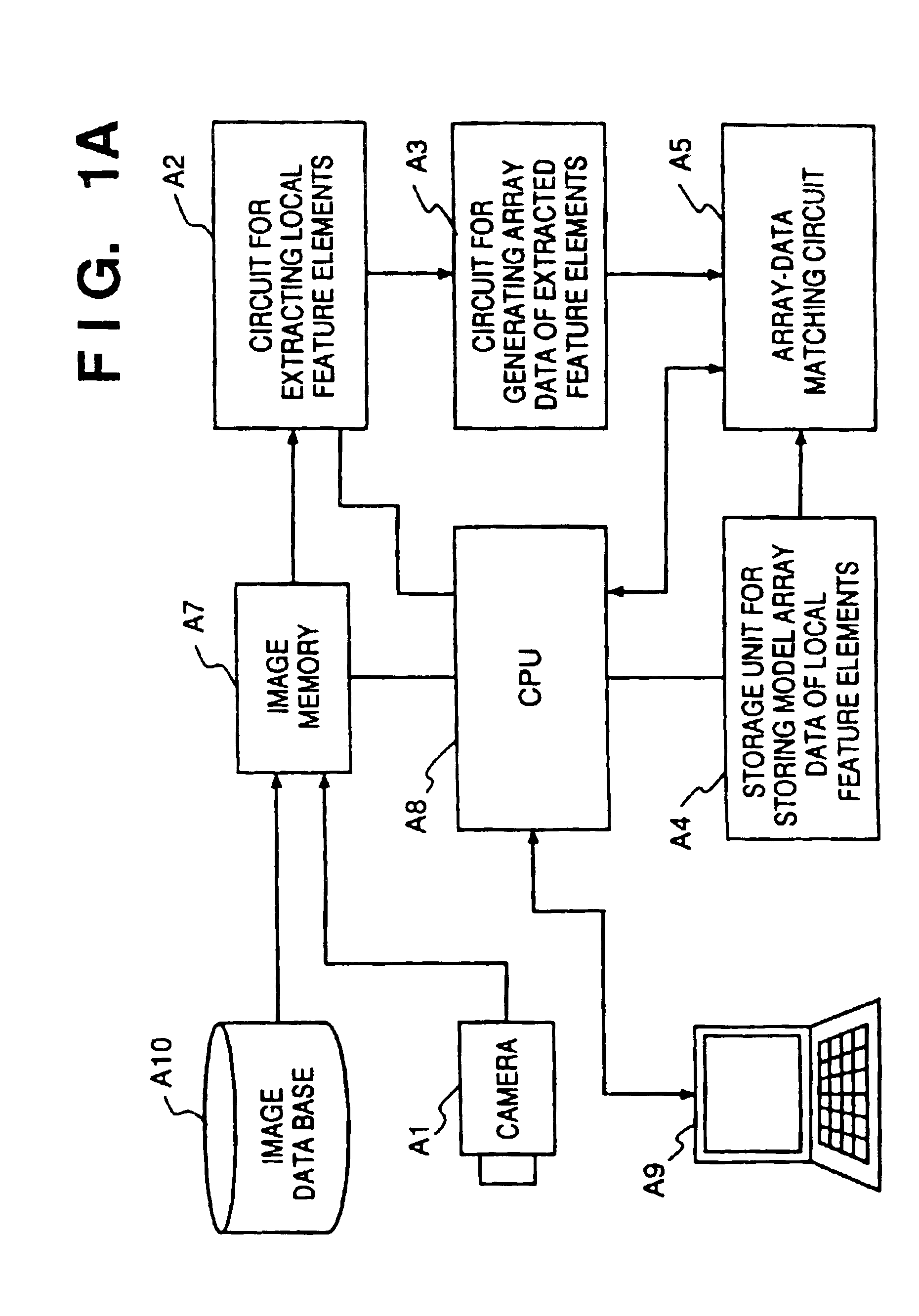
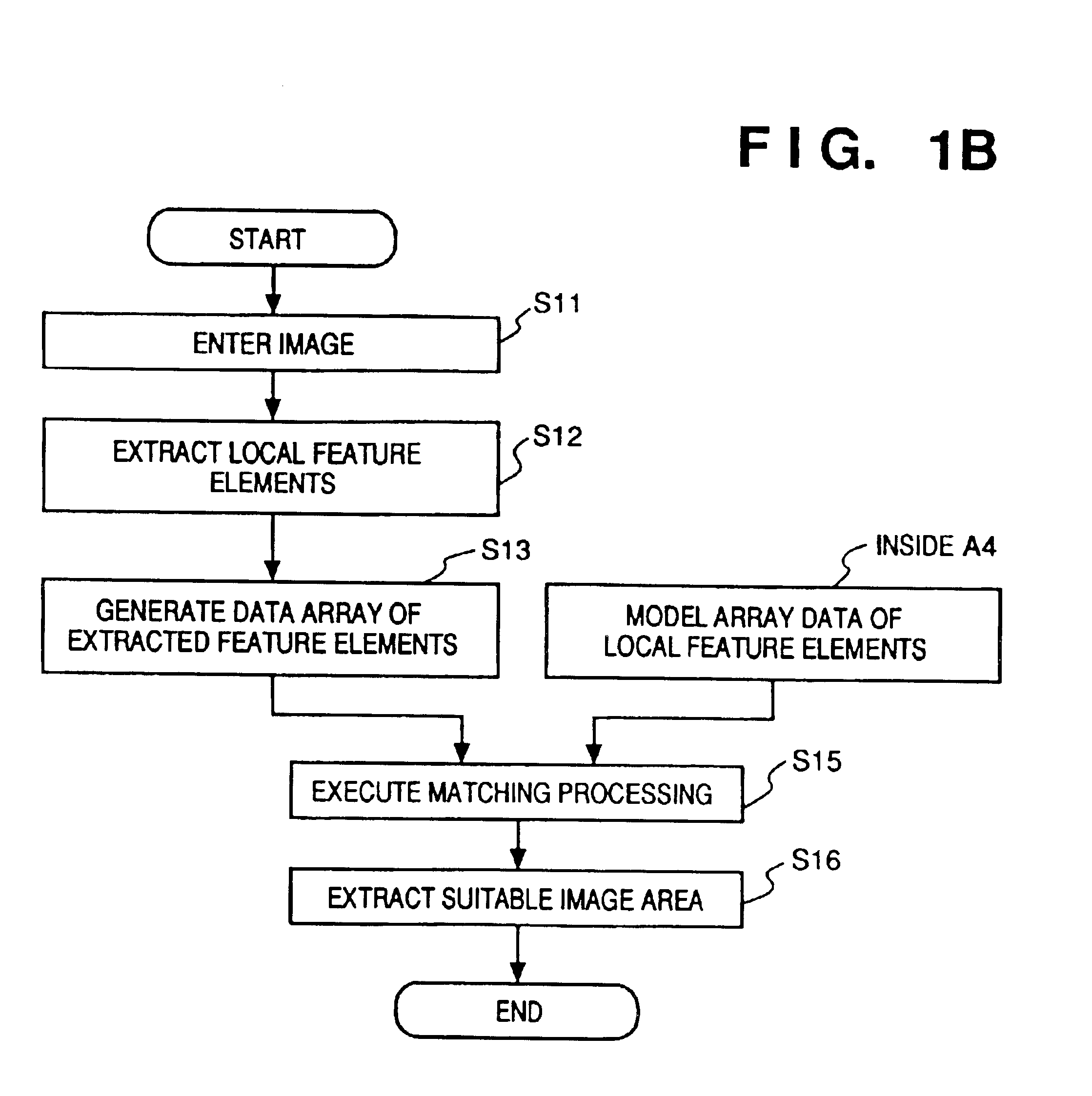
[0045]FIG. 1B is a flowchart of recognition processing in the present invention. At step S11, image data obtained from the camera A1 is recorded in the image memory A7. Next, at step S12, the circuit A2 for extracting local feature elements is used to extract, in each area of the image, a limited number of local feature elements, of a plurality of scales (sizes), set in advance by a scaling parameter σ. In this case, data other than that representing the extracted local feature elements is not held. Examples of the local feature elements are those constituted by intersection patterns (L-, T-, X- and Y-type intersections, etc.) of various edge segments and line segments (curves) such as curve segments having various curvatures (assumed to be fixed) and orientations. The scaling parameter σ indicates a scaling ratio with respect to a basic unit “1”, which serves as the basic unit of the resolution of the original image that has entered from the camera A1. At step S13, each local featu...

second embodiment

[0063

[0064]FIG. 5 is a structural view of three-dimensional lattice space in a second embodiment of the present invention. According to the second embodiment, a three-dimensional spatial relationship of the local feature elements described in the first embodiment is acquired and modeled. Techniques for three dimensional measurement that can be mentioned include a method of extracting corresponding points from an actual photographic image (e.g., a stereoscopic image obtained by photography using two cameras spaced by a prescribed distance from each other) by image processing, a method of measuring the phase of reflected light upon irradiation with a laser beam, and a method of projecting a structural pattern (a mesh pattern or the like) and measuring the degree of deformation thereof.

[0065]In FIG. 5, the cell shape of the lattice space is a shape obtained by dividing up a sphere equally in the directions of longitude and latitude. However, the cell shapes may be obtained by dividing ...

third embodiment

[0067

[0068]FIG. 6 is a flowchart of recognition processing in a third embodiment of the present invention. Steps S61, S62a and S65 in FIG. 6 are similar to steps S11, S12 and S15, respectively, in FIG. 1. At step S62b, area information such as the representative color, average luminance and local spatial frequency of a neighboring area which includes local feature elements is acquired for each array block of a size conforming to the scaling parameter σ. The image entered at step S61 is subjected to the above-described processing at steps S62a, S62b. At step S63a, array data is generated from the above-mentioned local feature elements and area information acquired at steps S62a, 62b. It is assumed that model array data of extracted local feature elements and area information has been stored in the model array data storage unit A4 (FIG. 1) for each block of an image, which is to undergo recognition, partitioned beforehand by square blocks conforming to the scaling parameter σ.

[0069]A ...


PUM


Abstract

An image recognition / reproduction method includes an extraction step of extracting local feature elements of an image, and a selection step of selecting a pair composed of a prescribed local feature element and position information indicative thereof, this pair being such that the distance between a pair composed of a prescribed local feature element and position information indicative thereof and a pair composed of a local feature element extracted at the extraction step and position information indicative thereof is less than a prescribed distance.

Description

[0001]This is a continuation of application Ser. No. 08 / 893,929, filed Jul. 15, 1997, now U.S. Pat. No. 6,463,176, which is a continuation of application Ser. No. 08 / 383,017, filed Feb. 2, 1995, now abandoned.BACKGROUND OF THE INVENTION[0002]This invention relates to a method and apparatus for recognizing objects and for reproducing the images of objects.[0003]Description of the Related Art[0004]One known example of a conventional method of displaying figure patterns or the like is a technique used in inputting figures as disclosed in the specification of Japanese Patent Publication (KOKOKU) No. 5-36830. The technique includes expressing the bent portion of the stroke of a geometrical figure symbol by one of various bend patterns (shape primitives) prepared in advance and approximating curves by circular arcs. The technique is applicable to recognition of geometrically simple figures.[0005]Further, an example of a method of recognizing objects is employed in an object recognition ap...

Claims


Application Information

Patent Timeline
Patent Type & Authority Patents(United States)
IPC IPC(8): G06T11/60G06K9/00G06K9/46G06V10/44
CPCG06K9/00268G06T11/60G06K9/4604G06V40/168G06V10/44
Inventor MATSUGU, MASAKAZUIIJIMA, KATSUMI
Owner CANON KK
Why Eureka
Try Eureka