Drawing compass

a compass and compass technology, applied in the field of drawing compass, can solve the problems of affecting the use requiring delicate control and balance, and hindering the scribing of the marking tip, etc., and achieve the effect of simple manufacture and convenient us

Inactive Publication Date: 2005-06-21
HAN KEDU +1
View PDF17 Cites 17 Cited by
  • Summary
  • Abstract
  • Description
  • Claims
  • Application Information

AI Technical Summary

Benefits of technology

[0011]The drawing compass of the present invention...

Problems solved by technology

Although traditional compasses have been used for many years, they have intrinsic deficiencies in usage.
It requires a delicate control and balance of pressure applied on the two legs to keep one leg anchored at the center and the other rotating and scribing on the drawing surface while twisting and rotating the handle.
It is difficult, as th...

Method used


Image

  • Drawing compass
  • Drawing compass
  • Drawing compass

Examples


Embodiment Construction

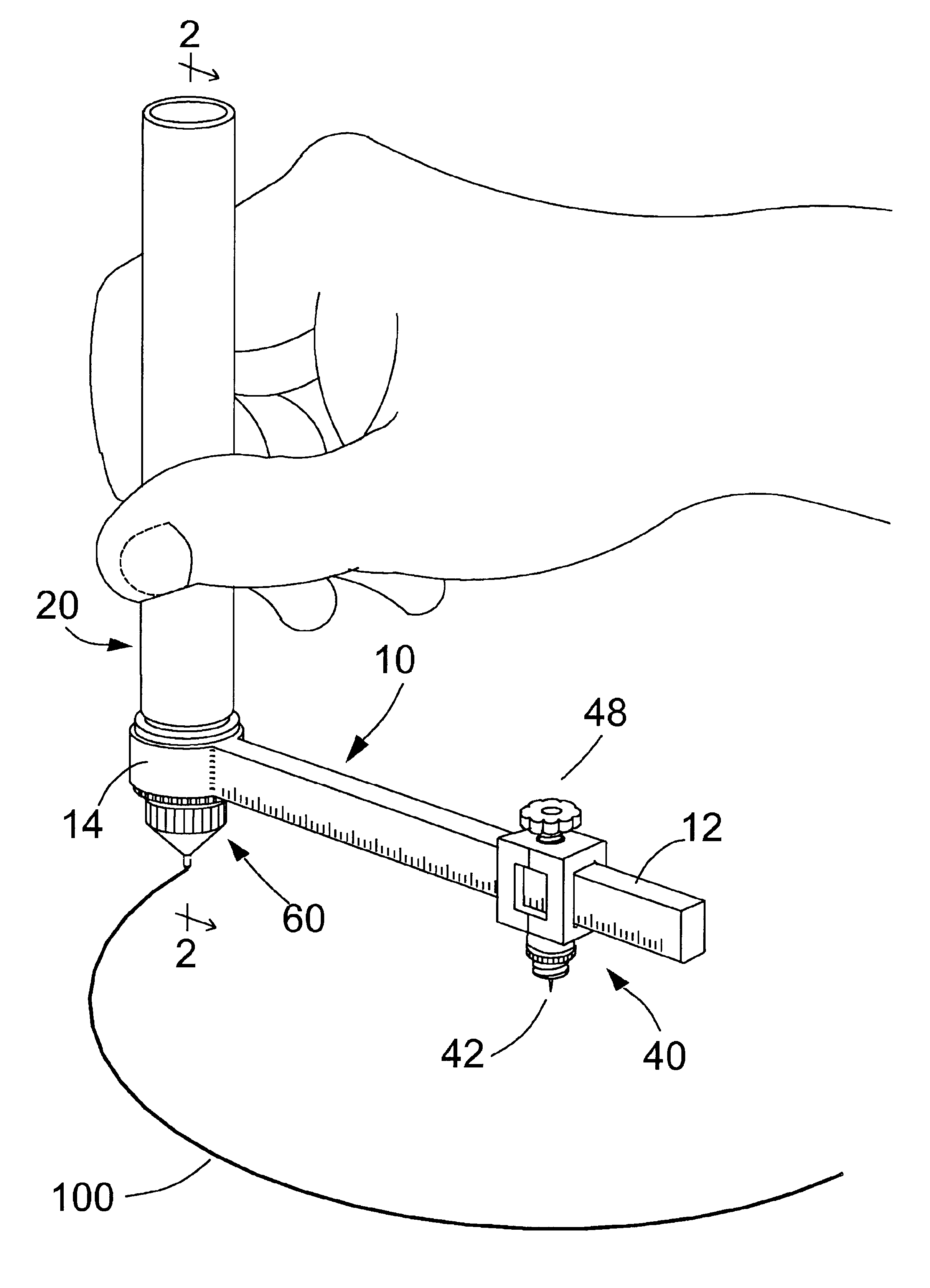
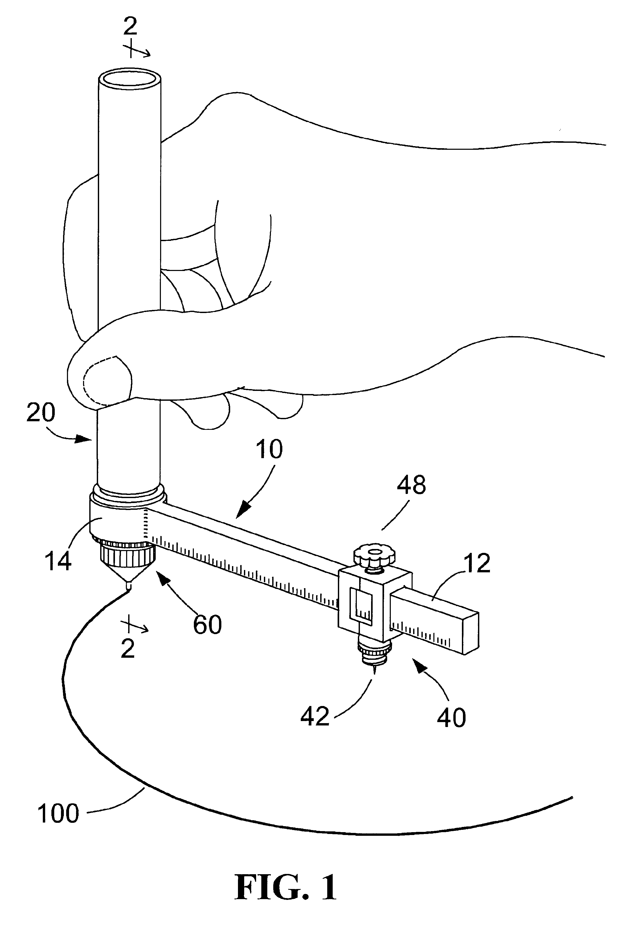
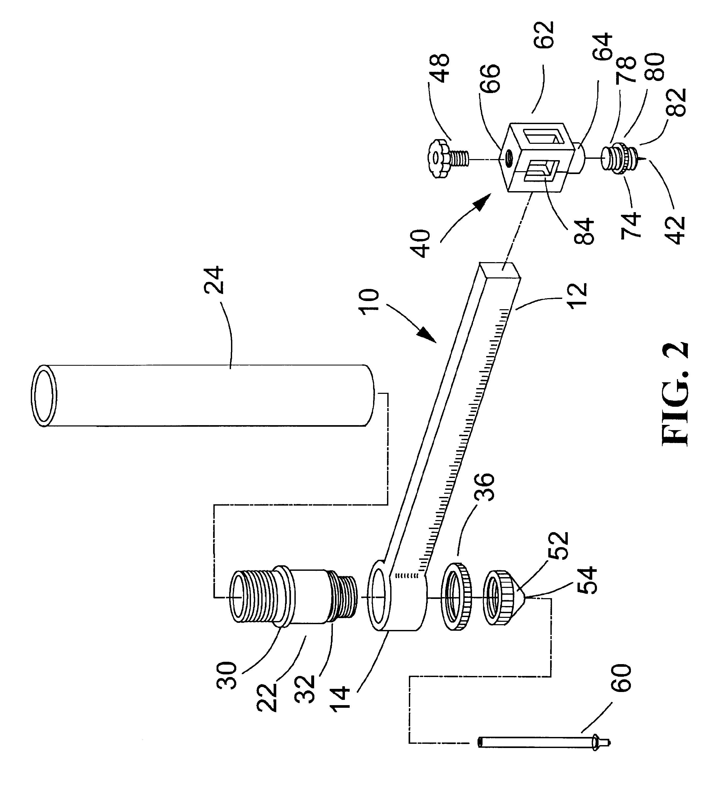
[0022]Referring to the drawings wherein like numerals refer to like parts, FIG. 1 illustrates the use of a preferred embodiment of the drawing compass according to the present invention. The drawing compass comprises an arm 10, an elongated handle 20, a marking instrument 60 mounted on the underside of handle 20, and a pivot pin holder 40 slidably mounted on arm 10. The arm 10 comprises an elongated bar portion 12 and a cylindrical portion 14. Indicia may be placed on elongated bar portion 12 for setting desired radius, as illustrated in FIG. 1. The handle 20 is rotatably mounted on cylindrical portion 14 of arm 10. The vertical handle 20 and horizontal arm 10 form a shape of capital letter L. The pivot pin holder 40 is secured by a securing bolt 48 at a desired position on arm 10. A pointed end 42 of pivot pin holder 40 is placed at the center of a circle 100. The handle 20 is held and positioned substantially perpendicular to the drawing plane and moved along circle 100 to trace o...


PUM


Abstract

A drawing compass with a structure of L shape and a method of using the same provide improved single-hand manipulation and handling of drawing an arc or circle. The drawing compass comprises a handle rotatably mounted on one end of an arm and a pivot pin holder slidably mounted along the arm. One can make an arc or circle by simply holding the handle perpendicular to a drawing surface, placing the pivot pin at the center and making a circular motion guided by the arm of the compass. In the drawing process, the pressure applied on the marking point is directly controlled by hand. The compass is easy to use, inexpensive, and simple to manufacture.

Description

BACKGROUND OF INVENTION[0001]This invention relates to a drawing compass, and more specifically to a novel compass apparatus and the method of using the same.[0002]Drawing compasses are well known as instruments for marking circles or arcs on draft paper or other surfaces. A traditional compass usually comprises of a handle and two legs with their upper ends pivotally attached to the handle. The free end of the first leg may be a pin or stylus.[0003]The free end of the second leg may be a marking instrument such as a pencil, pen or chalk. The free ends of the legs can be moved open or close so that the distance between the pin and the tip of the marking instrument can be adjusted to a desired radius of a circle or arc. The compass is used by placing the pin of the first leg at the center, placing the marking tip at a start point of the circle or arc to be drawn, and twisting the handle to rotate the second leg around the first one with the marking tip scribing on the drawing surface...

Claims


Application Information

Patent Timeline
IPC IPC(8): B43L9/00B43L9/02B43L9/04B43K29/00B43L9/24
CPCB43K29/001B43L9/24B43L9/04
Inventor HAN, KEDUHAN, KEHAN
Owner HAN KEDU
Why Eureka
Try Eureka