Cooling apparatus for a work machine

a technology for cooling equipment and work machines, applied in indirect heat exchangers, light and heating equipment, transportation and packaging, etc., can solve the problems of troublesome work, difficult to put cleaning tools, and difficult to remove cleaning tools, etc., to achieve easy discharge, easy attachment/detachment of cooling equipment, and good maintainability

Inactive Publication Date: 2005-06-21
T RAD CO LTD
View PDF15 Cites 36 Cited by
  • Summary
  • Abstract
  • Description
  • Claims
  • Application Information

AI Technical Summary

Benefits of technology

[0019]According to the still another aspect, since a part of the fan shroud is detachable, only a part of the fan shroud is removed, thereby attaching/detachi...

Problems solved by technology

However, the above conventional techniques have the following problems.
For this reason, the work is troublesome and takes a lot of time.
In the third example, since the oil cooler 64 is tiltable forward, the front upper portion of the radiator 63 can ...

Method used


Image

  • Cooling apparatus for a work machine
  • Cooling apparatus for a work machine
  • Cooling apparatus for a work machine

Examples


Embodiment Construction

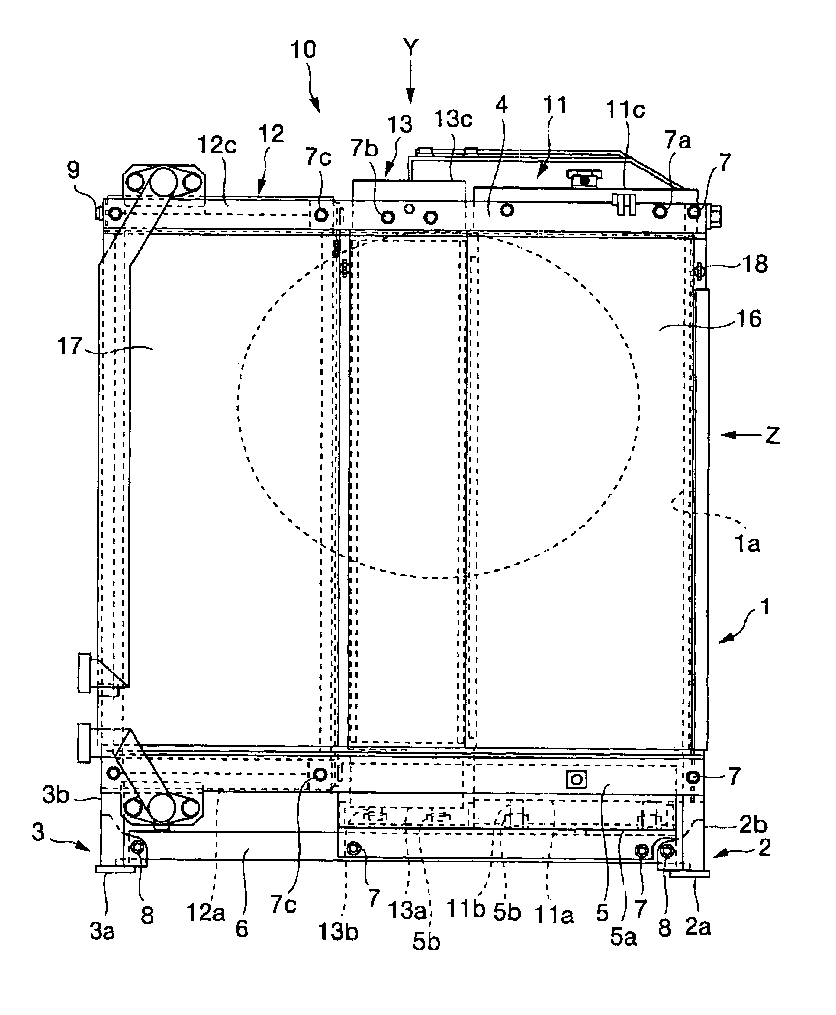
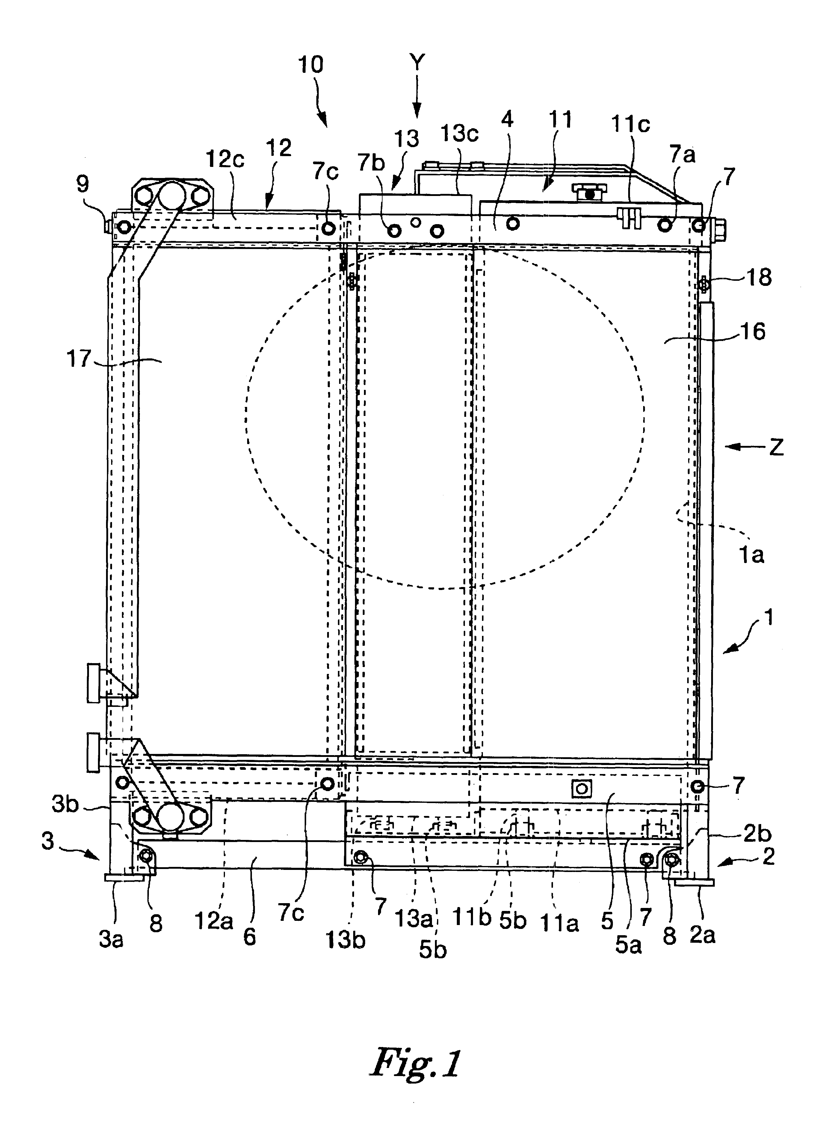
[0029]There will be explained below a cooling apparatus of a work machine according to embodiments of the present invention referring to FIGS. 1 through 6.

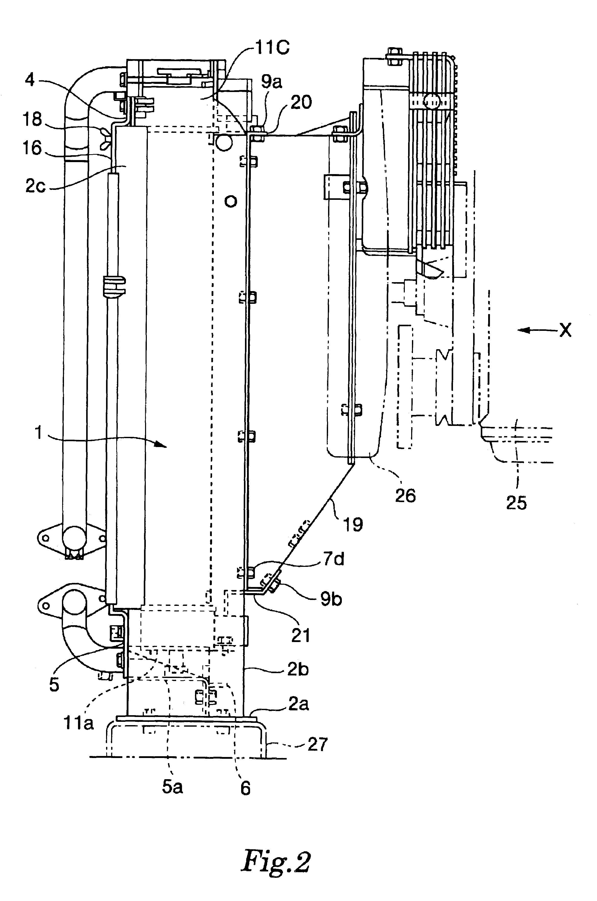
[0030]Firstly, the first embodiment will be explained referring to FIGS. 1 through 5. FIG. 1 is a front view of a cooling apparatus according to the first embodiment, FIG. 2 is a Z view of FIG. 1, and FIG. 3 is a Y view of FIG. 1. Moreover, FIG. 4 is an X view of FIG. 2 and FIG. 5 is a perspective view of a fan shroud.

[0031]As shown in FIGS. 1 through 4, in the cooling apparatus 10, a frame 1 which forms an opening portion la on a ventilation passage of a fan 26, is provided on an upper stream side of the fan 26 attached to an engine 25. A radiator 11, an oil cooler 12 and an after cooler 13 are arranged in parallel at the opening portion la of the frame 1 so that their front surfaces are approximately flush with one another.

[0032]The frame 1 has left and right frames 2 and 3 which stand on a body frame 27 and upper and lower brac...


PUM


Abstract

A cooling apparatus of a work machine which facilitates maintenance such as cleaning, check and remedy of cooling equipments such as a radiator, an oil cooler and an after cooler is provided. A frame which forms an opening portion on a ventilation passage is provided on an upper stream side of a fan, and a radiator and an oil cooler or a radiator and an oil cooler and an after cooler are arranged in parallel at the opening portion of the frame. At least one of the radiator and the oil cooler or at least one of the radiator and the oil cooler and the after cooler is mounted to the frame detachably. A fan shroud is mounted to the frame. A part of the fan shroud may be detachable.

Description

BACKGROUND OF THE INVENTION[0001]1. Field of the Invention[0002]The present invention relates to a cooling apparatus for a work machine.[0003]2. Description of the Related Art[0004]A radiator for radiating a heat of cooling water of an engine, and an oil cooler for radiating a heat of hydraulic fluid of a hydraulic equipment are necessary for a work machine. Further, in recent years, in order to heighten an intake air efficiency of an engine so as to heighten an engine performance, an after cooler for cooling a compressed supercharged air is adopted. Some techniques, which arrange such cooling equipments so as to heighten a cooling efficiency and take a maintainability and compactness of an installation space into consideration, have been conventionally suggested.[0005]The first example is a cooling apparatus of a work machine disclosed in Japanese Patent Application Laid-Open No. H11-350530 (1999), and FIG. 7 is an arrangement diagram of the cooling apparatus described in this publ...

Claims


Application Information

Patent Timeline
IPC IPC(8): F28F9/00F28D1/04B60K11/04E02F9/00
CPCF28F9/002F28D1/0443E02F9/00
Inventor KOYAMA, HITOSHI
Owner T RAD CO LTD
Why Eureka
Try Eureka