Method for molding optical fiber fusion spliced portion and optical fiber with molded fusion spliced portion

a technology of fusion spliced and optical fiber, which is applied in the direction of cladded optical fibre, instruments, other domestic articles, etc., can solve the problems of cracking on the mold/coating interface, inability to fully prevent the cracking on the interface, and more likely to occur cracks, etc., to achieve less shrinkage and increase operation efficiency without reducing strength

Inactive Publication Date: 2005-06-21
SUMITOMO ELECTRIC IND LTD
View PDF5 Cites 18 Cited by
  • Summary
  • Abstract
  • Description
  • Claims
  • Application Information

AI Technical Summary

Benefits of technology

[0013]The present invention has been achieved in the light of the above-mentioned problems. It is an object of the invention to provide a method for molding an optical fiber fusion spliced portion in which a fusion spliced portion of the optical fibers can be molded to have an outer diameter close to that of the coating of the optical fibers without causing a crack on a mold / coating interface and an exfoliation in an overlap portion. It is another object of the invention to provide an optical fiber with a molded fusion spliced portion.
[0017]With this method, since the molding resin has a large tensile elongation and a high tensile strength, it is possible to withstand a shrinkage force when the molding resin is cured, and prevent the crack from occurring on the mold / coating interface. Thereby, it is unnecessary to make the coating at the top end of the optical fiber thin as same as related art, so that the operation efficiency can be increased without reducing the strength.
[0020]With this method, since the adhesion of the molding resin with the outermost layer coating of the optical fiber is strong, it is possible to prevent an exfoliation in the overlap portion by withstanding a shrinkage force when the molding resin is cured. Thereby, it is unnecessary to thin the coating at the top end of the optical fiber as same as related art, so that the operation efficiency can be increased without reducing the strength.
[0024]With this method, since the curing shrinkage percentage of the molding resin itself is low, there is less shrinkage when the molding resin is cured, whereby it is possible to prevent the crack on the mold / coating interface and the exfoliation in the overlap portion. Thereby, it is unnecessary to thin the coating at the top end of the optical fiber as same as related art, so that the operation efficiency can be increased without reducing the strength.
[0025]To prevent the crack on the mold / coating interface and the exfoliation in the overlap portion, it is preferable that the curing shrinkage percentage of the molding resin is 5.5% or less.

Problems solved by technology

Therefore, there are some cases where a braking occurs from an end of a mold / coating interface between the mold coating and the fiber coating due to a shrinkage of the injected molding resin when cured, and thus a crack occurs on the mold / coating interface.
In addition, since the molding resin 105 for use in molding has a large curing shrinkage percentage, and small tensile strength and small tensile elongation, there remains a problem that it is not possible to fully prevent the crack on an interface 107 between the molding resin 105 and the coating 101 that is caused by shrinkage of the injected molding resin 105, when cured.
In particular, the crack is more likely to occur when the screening (added tension) recoiling is performed.
Therefore, there is also a risk that the overlap portion 106 is exfoliated when making a wiping process with ethanol (ethanol wiping) to remove the excess resin such as fin-like object after curing the molding resin 105.
Further, there is a risk that the sand paper damages the glass, thereby resulting in reducing the fiber strength.

Method used


Image

  • Method for molding optical fiber fusion spliced portion and optical fiber with molded fusion spliced portion
  • Method for molding optical fiber fusion spliced portion and optical fiber with molded fusion spliced portion
  • Method for molding optical fiber fusion spliced portion and optical fiber with molded fusion spliced portion

Examples


Embodiment Construction

[0032]The preferred embodiments of the present invention will be described below in detail with reference to the accompanying drawings.

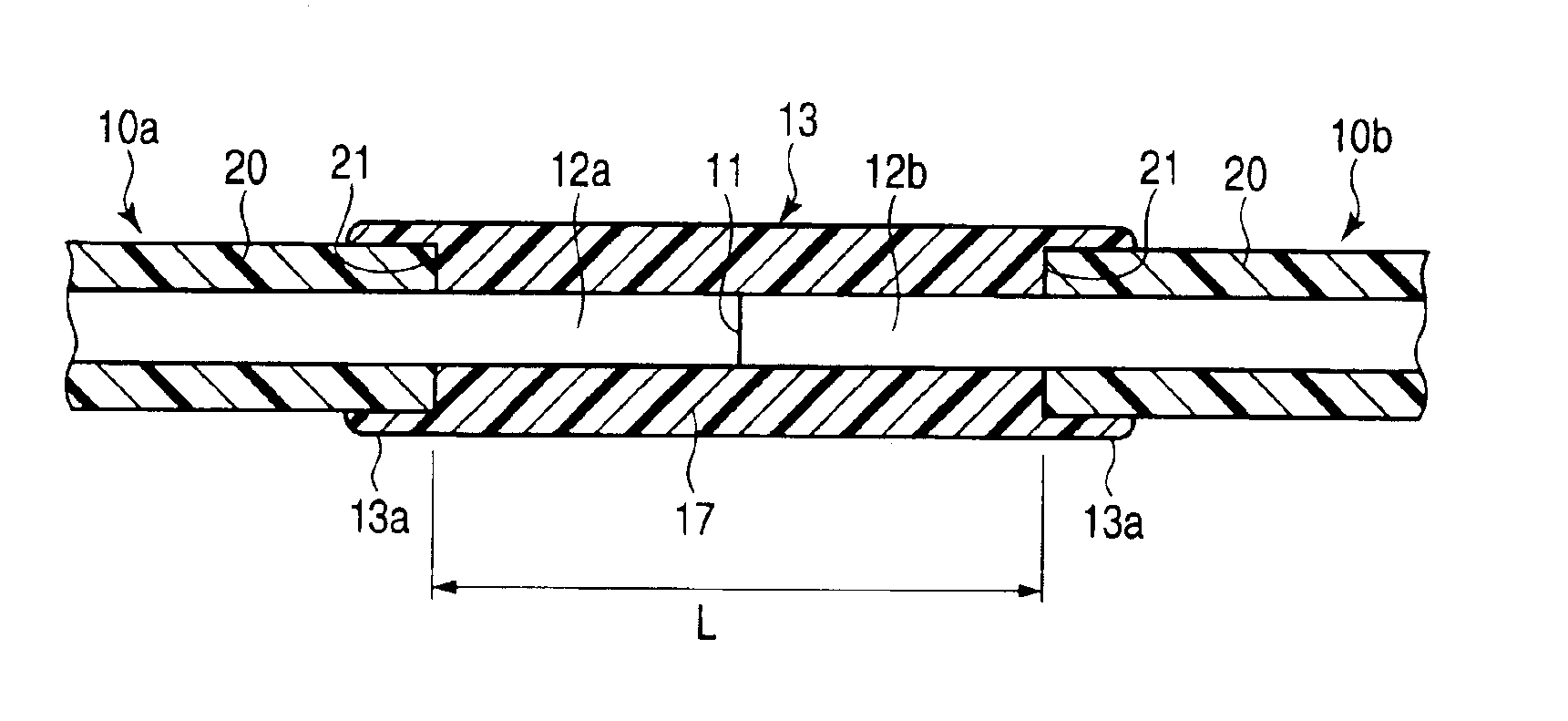
[0033]A method for molding an optical fiber fusion spliced portion of the present invention includes forming a mold coating 13 on bare fiber portions 12a and 12b of optical fibers 10a and 10b over a fusion spliced portion 11, with a resin compound 17, as shown in FIG. 1. The resin compound 17 of the present invention has the characteristics where in a cured state, the tensile elongation is 70% or more and the tensile strength is 20 Mpa or more.

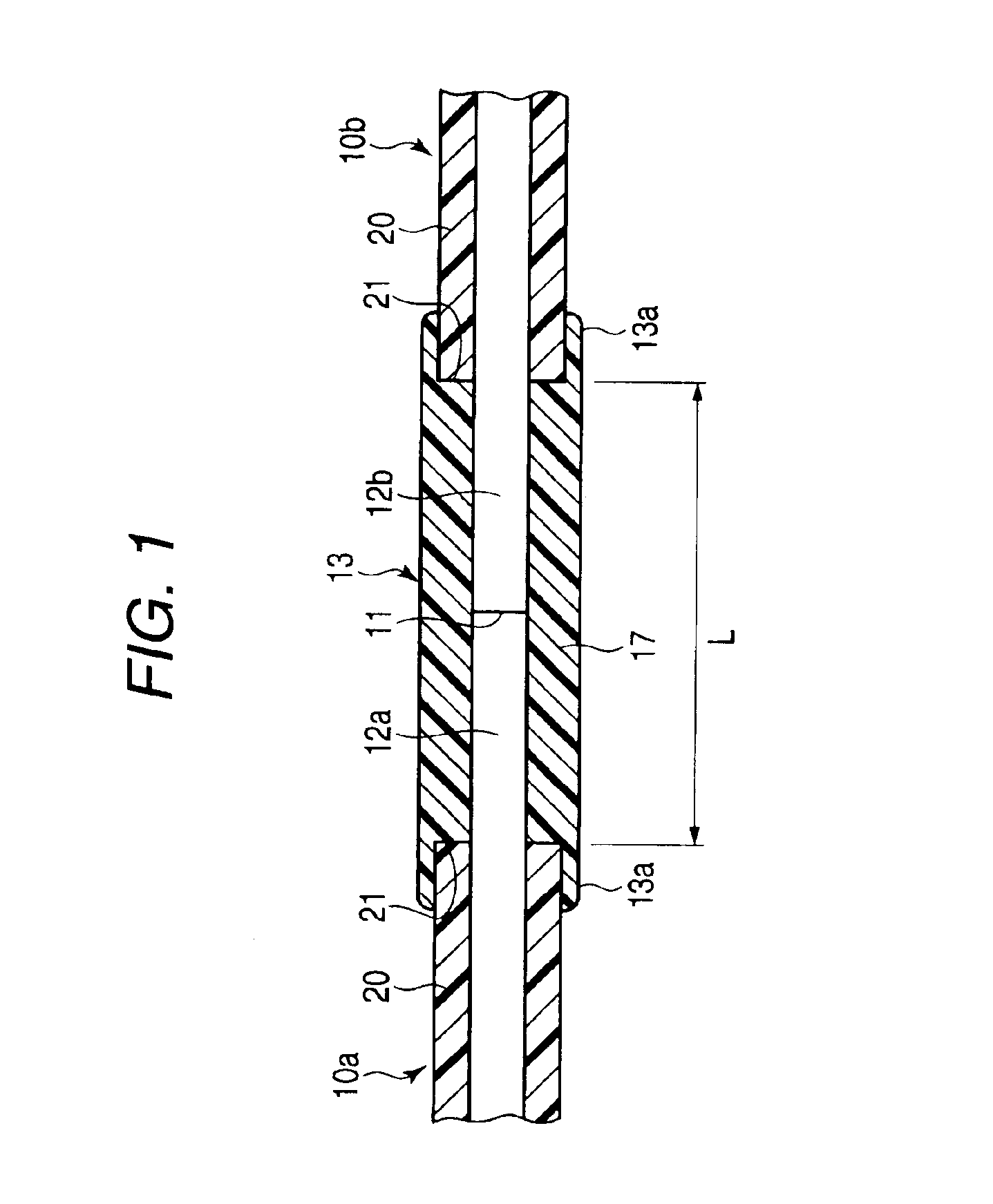
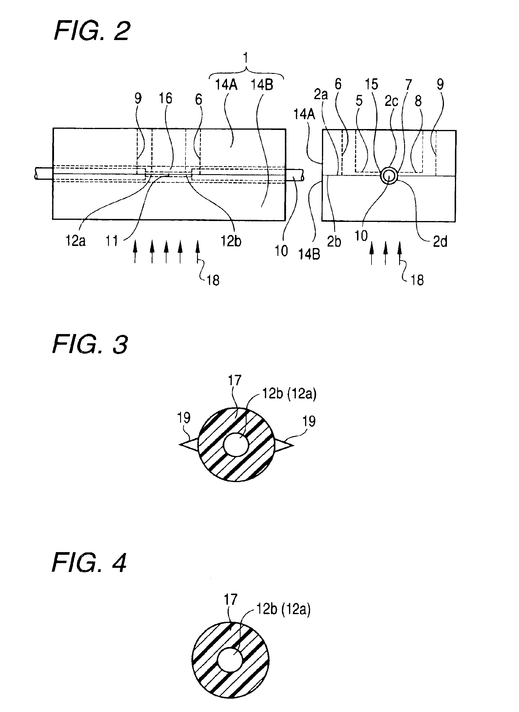
[0034]For example, as shown in FIGS. 2 to 4, the bare fiber portions 12a and 12b for the optical fiber fusion spliced portion 11 of the optical fiber 10 are placed between upper and lower mold tools 14A and 14B (which is shown in EP1197311A1). A ultraviolet curable resin as the resin compound having the previously mentioned characteristics is supplied as a molding resin 17 through a resin injection gate 15 of t...


PUM

PropertyMeasurementUnit
tensile strengthaaaaaaaaaa
tensile elongationaaaaaaaaaa
adhesionaaaaaaaaaa

Abstract

In a method for molding an optical fiber fusion spliced portion, a mold coating is formed on a bare fiber portion of a fusion spliced portion of the optical fibers, using a resin compound having the characteristics where in a cured state, the tensile elongation is 70% or more and the tensile strength is 20MPa or more.

Description

BACKGROUND OF THE INVENTION[0001]1. Field of the Invention[0002]The present invention relates to a method for molding an optical fiber fusion spliced portion, and an optical fiber with a molded fusion spliced portion. More particularly, the present invention relates to a method for molding an optical fiber fusion spliced portion to mold (recoat) an exposed portion of the fusion spliced optical fiber again, for example.[0003]2. Description of the Related Art[0004]It is required to produce a long distance optical transmission line in which the closure or terminal box can not be installed, for example, an optical fiber submarine cable of several tens kilometers long. In manufacturing the optical fiber cable, the optical fibers being shorter than a certain cable length are spliced with the characteristics of high strength. In such optical fiber cable, the shape and the outer diameter of the spliced portion must be almost equivalent to those of the coating of the optical fiber.[0005]In r...

Claims


Application Information

Patent Timeline
Patent Type & Authority Patents(United States)
IPC IPC(8): C03C25/12C03C25/10G02B6/38C03C25/106
CPCC03C25/106G02B6/2558C03C25/12
Inventor OISHI, KAZUMASAKOIKE, REI
Owner SUMITOMO ELECTRIC IND LTD
Why Eureka
Try Eureka