Door mounted deadman for exercise devices

a technology for dead bodies and exercise devices, applied in gymnastics, resistance force resistors, therapy exercises, etc., can solve the problems of large mechanical structures, damage to the door,

Inactive Publication Date: 2005-06-21
SAURE PAUL
View PDF7 Cites 125 Cited by
  • Summary
  • Abstract
  • Description
  • Claims
  • Application Information

AI Technical Summary

Benefits of technology

[0010]In what follows, I solve this deficiency by first constructing a strap deadman which optimally strains a door by tension only into the door's jambs and lintels so that a vertically disposed strap on a face of the door can act as the deadman point of attachment. Secondly, I disclose a deadman having a plurality of attachment points. The resulting deadman cooperates with simple strain producing members—such as elastic tubes—which enable floor to ceiling anchor points enabling a full exercise vocabulary adaptable to any prescribed fitness regimen.
[0011]A door-mounted strap extends around a door in the vertical direction, from the top of the door to the bottom of the door to act as a deadman preferably toward an exerciser on the closing side of the door. The strap is continuous as it faces the exerciser. On the rear side of the door, away from the exerciser, the strap has a tension-locking clamp, typically a ladder lock, enabling the tightened strap to snugly surround the door. A back-mounting strip exceeds in width and underlies the door-mounted strap at least on the side of the doo

Problems solved by technology

I have discovered that such door-mounted devices suffer from at least two deficiencies.
First, most devices mount relatively large mechanical structures to the door in the form of pulleys, levers, top and/or bottom mounted (typically U-shaped) brack

Method used


Image

  • Door mounted deadman for exercise devices
  • Door mounted deadman for exercise devices
  • Door mounted deadman for exercise devices

Examples


Embodiment Construction

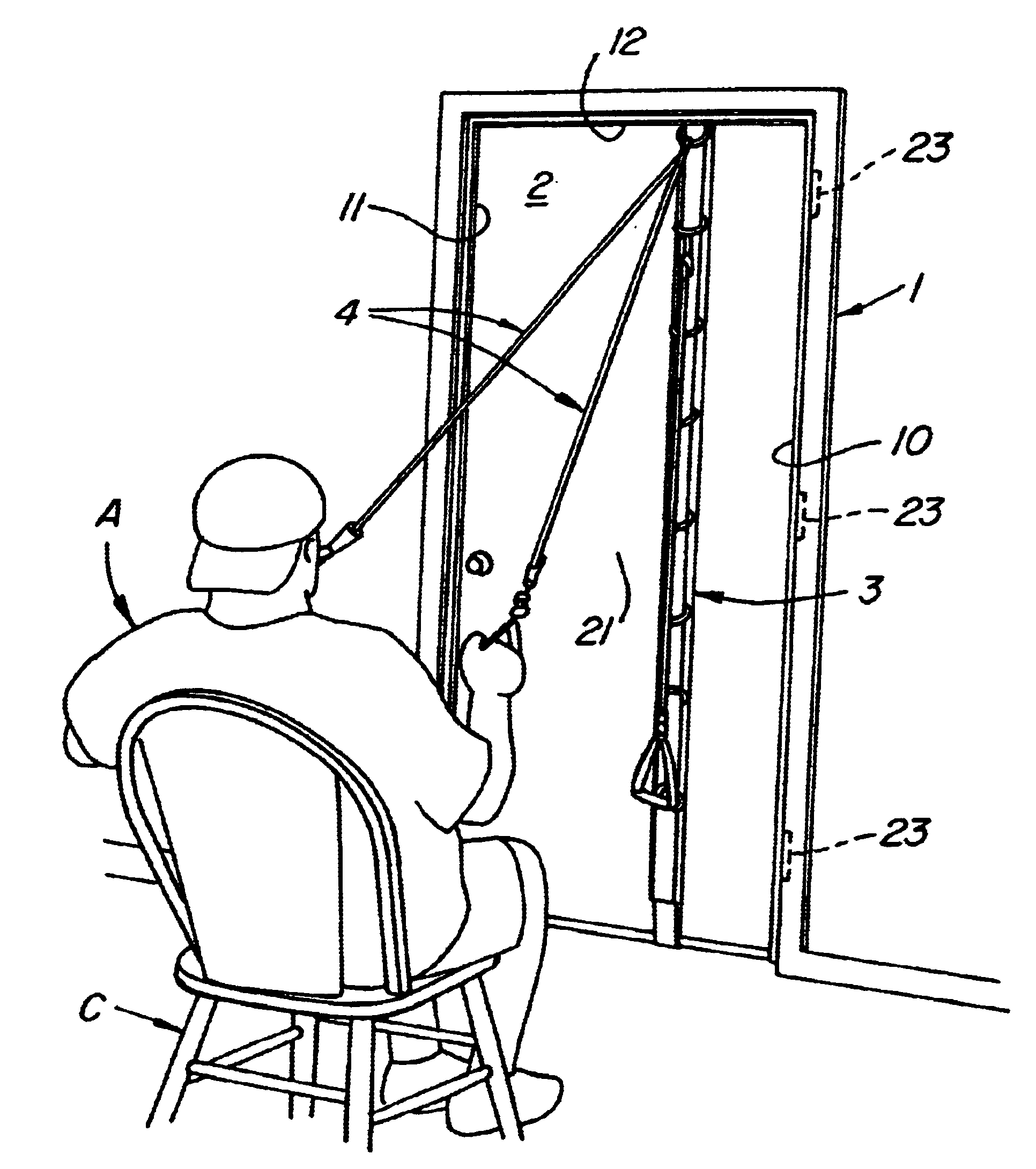
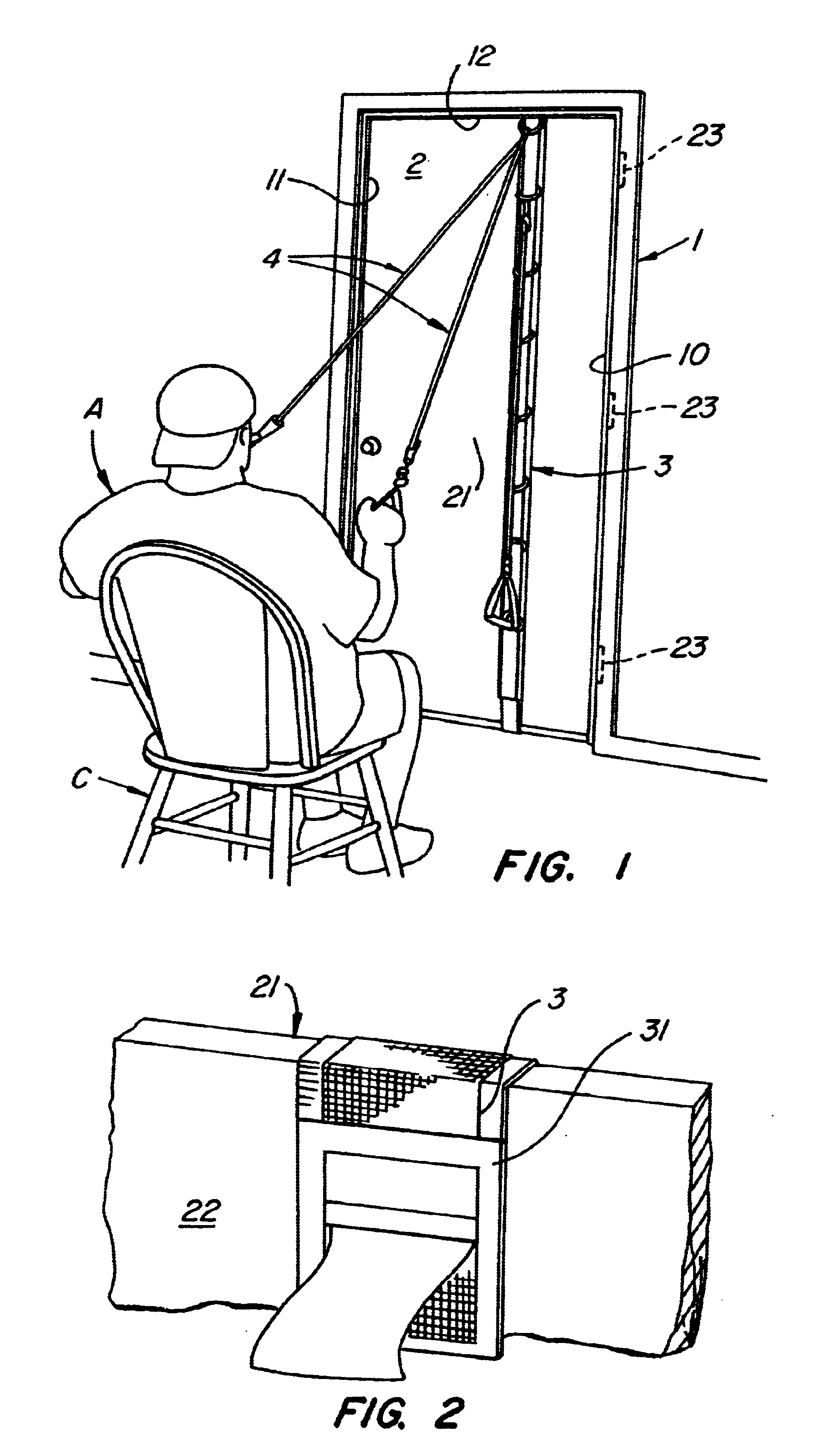
[0020]Referring to FIG. 1, door 2 is surrounded by strap 3. Exerciser A utilizing elastic exercise gear 4 fastened to strap 3 at door 2 undertakes exercise as he is seated in chair C. It is the purpose of this invention to set forth a completely portable and universally mounting exercise apparatus. In what follows we will describe each of the components of this invention. First strap 3 will be described. Thereafter mounting of the strap 3 to door 2 will be set forth. Finally, the threading of exercise gear 4 to the D-rings 33 will be set forth.

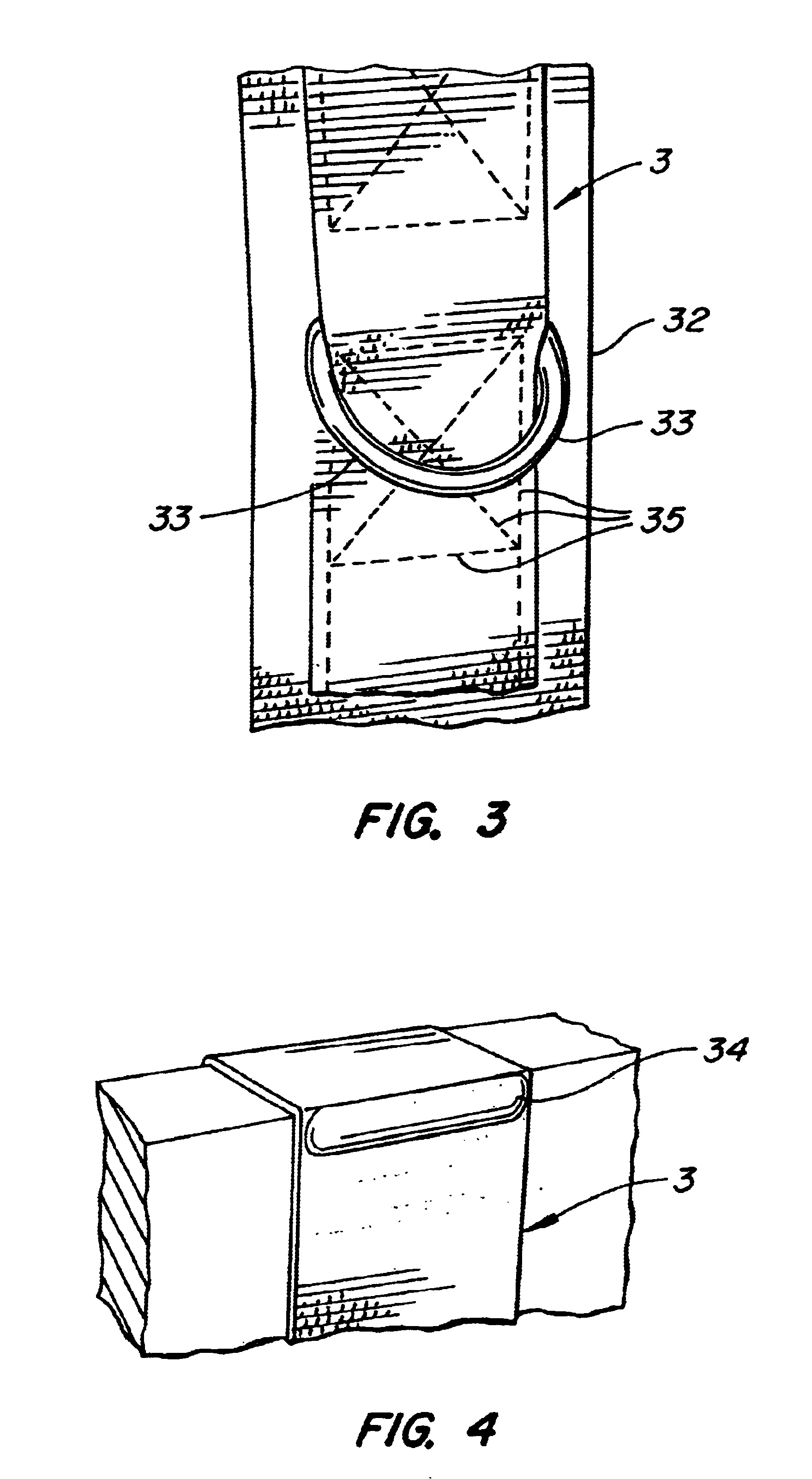
[0021]The construction of strap 3 is easily understood. Referring to FIG. 3, it will be seen that strap 3 extends along closing face 21 of door 2. Along this side of door 2, strap 3 has a backing strap 32 sewn between the strap and the door 2. Sewing of strap 3 to backing strap 32 occurs at stitching 35. During this sewing attachment, D-rings are fastened between the strap 3 and backing strap 32 at approximate 10-inch intervals along one side ...


PUM


Abstract

A door-mounted strap extends around a door in the vertical direction, typically being placed medially of the door. On the deadman side of the door, the strap is continuous as it faces the exerciser. On a face of the door, away from the exerciser, the strap has a tension-locking clamp, typically a ladder lock, enabling the tightened door-mounted strap to snugly surround the door. Extending from the door top to the door bottom on exerciser's side of the door is a back-mounting strip that exceeds in width and underlies the door-mounted strap. This back-mounting strip is sewn at intervals to enclose the horizontally disposed linear back members of D-rings at approximate 10-inch intervals. Removable and attachable elastic members are provided for fastening to the arcuate portions of the D-rings. These D-rings and elastic members are provided in combination with handholds, limb straps, at the like to enable standing, sitting or prone exercise positions between the D-rings at the deadman and the exerciser.

Description

[0001]This invention relates to a door attached deadman for an exercise devices. Specifically, a door mounted vertical strap cooperating with the door jambs and lintel is disclosed for providing any room with a door as a candidate location for wall mounted exercise devices.[0002]This application claims priority from Provisional Patent Application 60 / 357,365 filed Feb. 15, 2002 entitled Door Mounted Deadman for Exercise Devices.BACKGROUND OF THE INVENTION[0003]Doors have in the past been used for mounting a variety of exercise devices. Exemplary of such mountings are:[0004]Pollock U.S. Pat. No. 5,254,065 issued Oct. 19, 1993 entitled Flexible Loop Fastening Strap Supportable in Door Structure. In this disclosure, a strap having an enlarged end portion is trapped on one side of the door with a loop depending to the opposite side of the door. The loop acts as the anchored point from which a portion of an exercise device may be attached.[0005]McFall et al. U.S. Pat. No. 5,468,205 issued...

Claims


Application Information

Patent Timeline
IPC IPC(8): A63B21/16A63B21/00A63B21/02A63B21/055
CPCA63B21/0552A63B21/1645A63B21/1654A63B21/1663A63B21/0442Y10S482/904A63B2208/0204A63B2208/0233Y10S482/907
Inventor SAURE, PAUL
Owner SAURE PAUL
Why Eureka
Try Eureka