Surface mount crimp terminal and method of crimping an insulated conductor therein

a technology of crimp terminal and insulated conductor, which is applied in the direction of contact members penetrating/cutting insulation/cable strands, fixed connections, and connection formation by deformation, etc., can solve the problems of requiring substantial amount of real estate on the board, and achieves convenient and efficient use, excellent strain relief of wires, and fast, reliable and efficient mounting

Active Publication Date: 2009-09-22
ZIERICK MFG
View PDF41 Cites 9 Cited by
  • Summary
  • Abstract
  • Description
  • Claims
  • Application Information

AI Technical Summary

Benefits of technology

[0006]It is another object of the invention to provide a surface mount terminal that is simple in construction and economical to manufacture.
[0008]It is yet another object of the present invention to provide a terminal of the type under discussion which provides excellent strain relief for the wire.
[0009]It is a further object of the invention to provide a terminal of the type under discussion that can be readily and efficiently used with automatic pick and place equipment.
[0010]It is still a further object of the invention to provide a terminal as in the aforementioned objects which provides fast, reliable and efficient mounting on printed circuit boards and termination of insulated conductors therein which may have the insulation pre-stripped or pierced by the terminal during crimping.

Problems solved by technology

Most surface mount IDC's are fairly large, require substantial amount of real estate on the board because of their large footprints and do not provide good strain relief on the wire.

Method used


Image

  • Surface mount crimp terminal and method of crimping an insulated conductor therein
  • Surface mount crimp terminal and method of crimping an insulated conductor therein
  • Surface mount crimp terminal and method of crimping an insulated conductor therein

Examples


Embodiment Construction

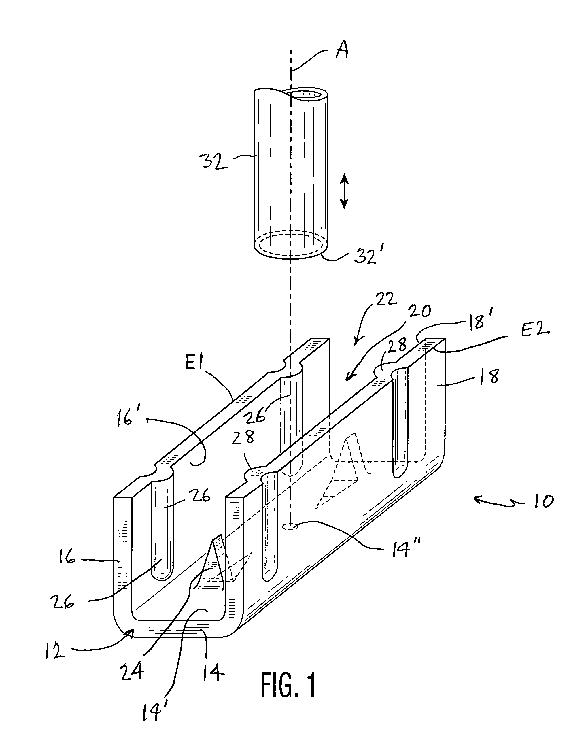
[0021]Referring now specifically to the Figures, in which the identical or similar parts are designated by the same reference numerals throughout, and first referring to FIG. 1, a surface mount (SM) insulation piercing crimp terminal in accordance with the present invention is generally designated by the reference numeral 10.

[0022]While the presently preferred embodiment to be described is for a surface mount insulation displacement connector (IDC) the invention also contemplates to use of such SM crimp connectors or terminals that have ends pre-stripped of insulation that can be similarly crimped.

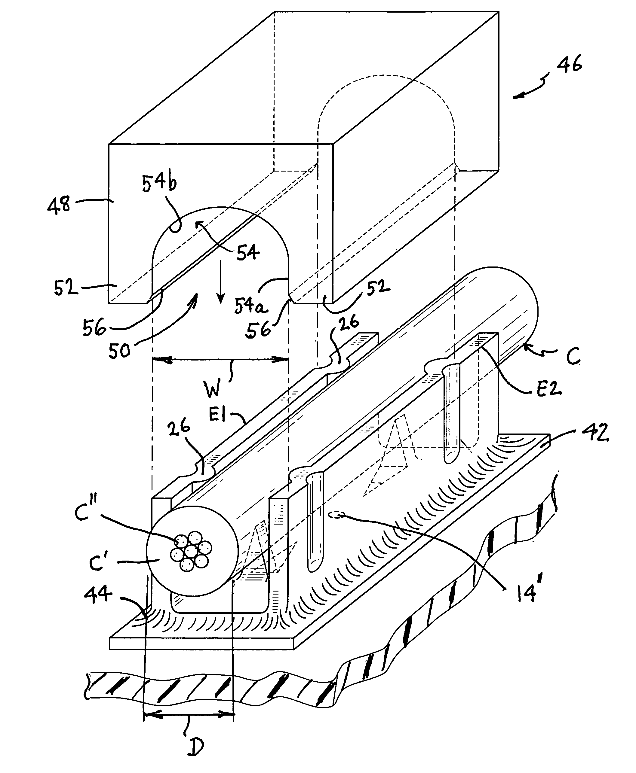
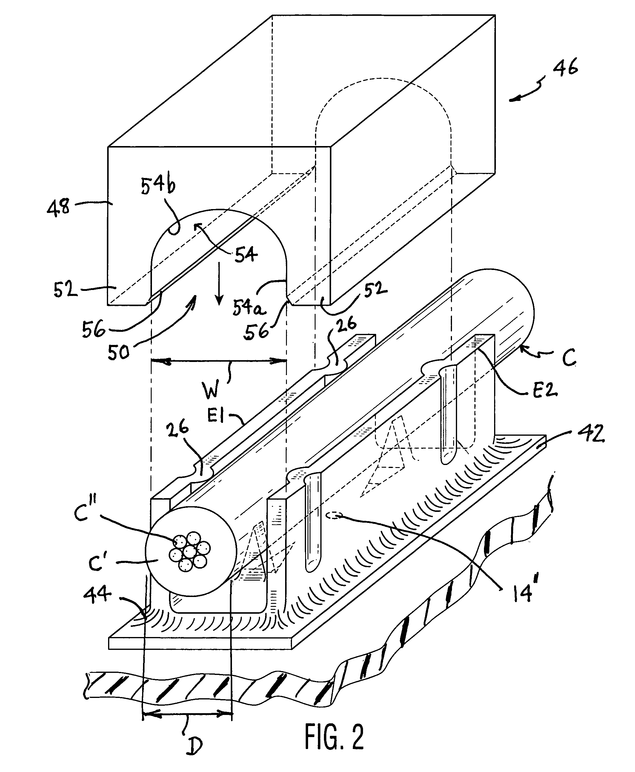
[0023]The terminal 10 is useful for connection to an insulated conductor C having a predetermined substantial uniform external cross-sectional dimension. In FIG. 2, the insulated conductor is shown to have a substantially uniform circular cross-sectional dimension having a diameter of D. The conductor C includes an sheath of electrical insulation C′ and central conductors or wires C″ imbed...


PUM

PropertyMeasurementUnit
lengthaaaaaaaaaa
surface areaaaaaaaaaaa
mechanicalaaaaaaaaaa

Abstract

A surface mount insulation terminal is formed of flat deformable conductive member to provide a substantially uniform U-shaped cross-section to form a wire-receiving channel. One or more piercing spikes are formed on a bottom wall of the channel and point to an opposing open side through which a conductor may be introduced. Ribs inside the channel provide an interference fit with a conductor introduced into the channel. A crimping tool lowered into engagement with the terminal after it has been soldered to a PCB increasingly deforms the side walls of the terminal inwardly towards each other and towards the bottom wall to enhance the electrical and mechanical properties of the resulting termination.

Description

BACKGROUND OF THE INVENTION[0001]1. Field of the Invention[0002]This invention generally relates to a electrical connectors and, more specifically, to surface mount crimp terminals and method of crimping insulated conductor therein.[0003]2. Description of the Prior Art[0004]Typically, to terminate a wire to a surface mount printed circuit board a two-piece connection system is used. Usually, a receptacle is crimped onto the wire and the mating tab or pin is surface mounted on the printed circuit board (“PCB”). A less expensive solution is a one terminal system like the insulation displacement connector (“IDC”). Most surface mount IDC's are fairly large, require substantial amount of real estate on the board because of their large footprints and do not provide good strain relief on the wire.SUMMARY OF INVENTION[0005]Accordingly, it is an object of the present to provide a surface mount crimp terminal that does not have the disadvantages inherent in such prior terminals or contacts.[0...

Claims


Application Information

Patent Timeline
Patent Type & Authority Patents(United States)
IPC IPC(8): H01R4/24
CPCH01R4/2404H01R12/57H01R4/2445Y10T29/49185H01R43/058
Inventor LEGRADY, JANOSTARULLI, RAFFAELLEFREDRIKS, RONALD
Owner ZIERICK MFG
Why Eureka
Try Eureka