
Circuit device for driving an AC electric load

a circuit device and load technology, applied in the direction of ac-dc conversion, electrical apparatus, control systems, etc., can solve the problems of low system efficiency, unacceptable system cost in low-end applications, and not even these approaches can achieve the harmonic content reduction of the supply lin

Inactive Publication Date: 2005-06-21
STMICROELECTRONICS SRL
View PDF10 Cites 13 Cited by
  • Summary
  • Abstract
  • Description
  • Claims
  • Application Information

AI Technical Summary

Benefits of technology

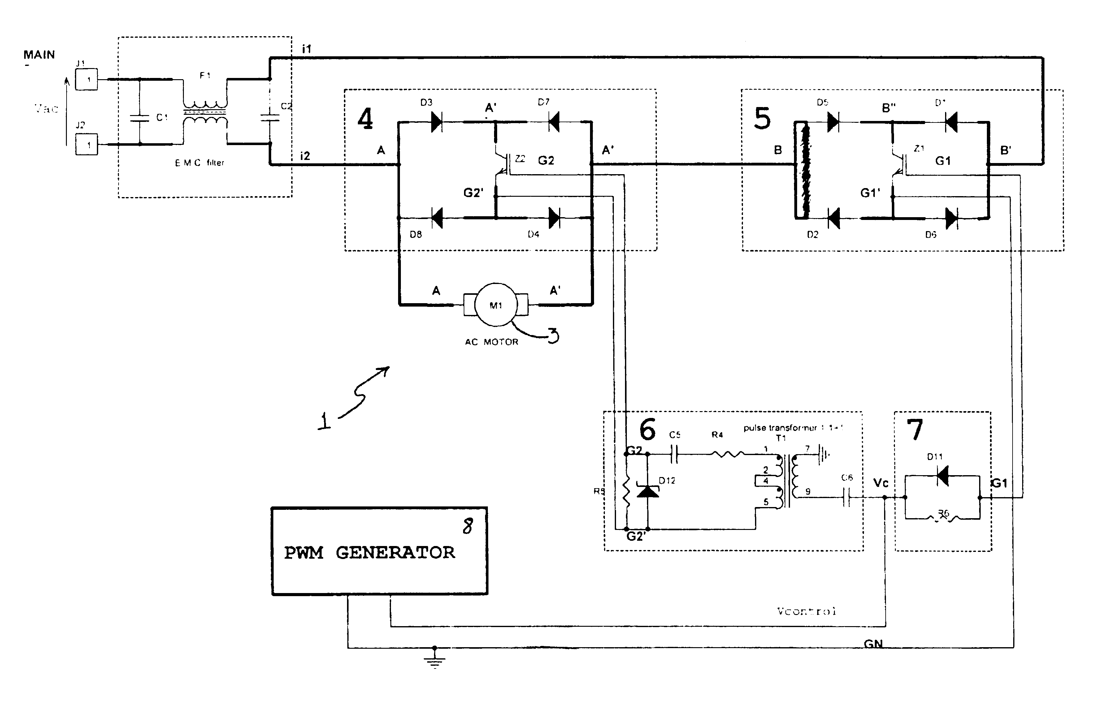
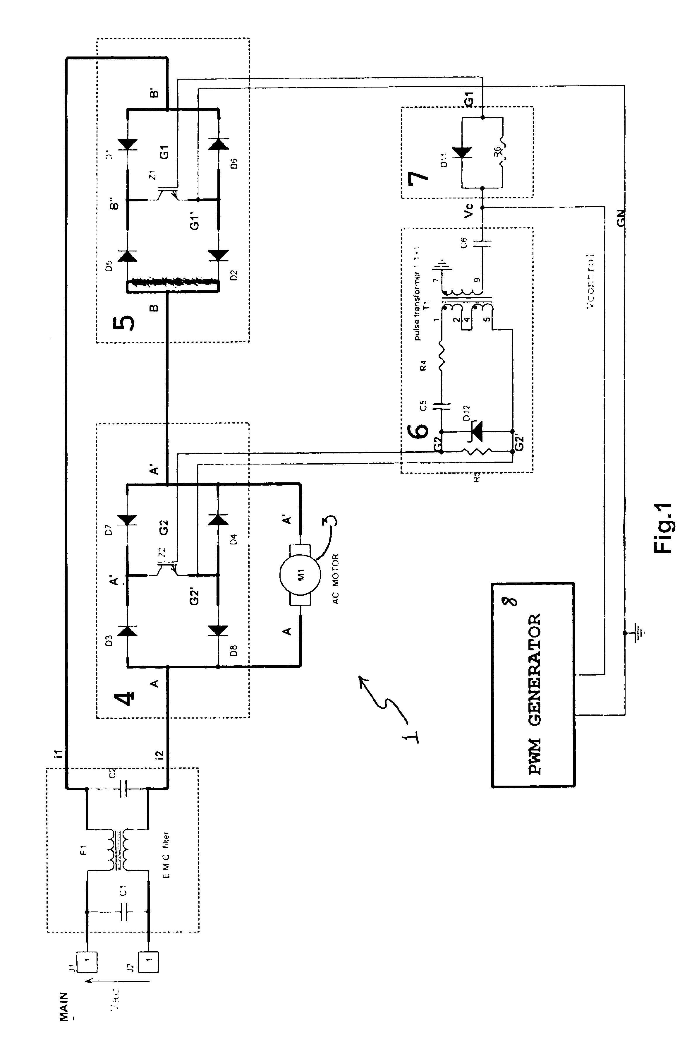
The invention is a circuit device that can connect directly to an AC power supply without any preliminary conversion, and can regulate the voltage and current to the load. This means that the device can be used with any AC load, regardless of its current-voltage offset, and can be used for different types of AC motors. The technical effect of this invention is to provide a more efficient and flexible solution for driving AC loads.

Problems solved by technology

This is a cost-effective technique that has been in use for decades, but has a problem in that harmonics are introduced in the current waveform of the power supply line, resulting in a low efficiency of the whole system.
However, not even these approaches have succeeded to lower the harmonic contents with respect to the supply line, because of the presence at the input of supply stages that employ rectifying bridges and filter capacitors, both introducing current distortions.
In all cases, inverter systems involve double conversion, AC to DC at the input and DC to AC at the output, as well as the use of complex modulation and control techniques normally implemented by microcontrollers that raise the system cost unacceptably in low-end applications.

Method used


Image

  • Circuit device for driving an AC electric load
  • Circuit device for driving an AC electric load
  • Circuit device for driving an AC electric load

Examples


Embodiment Construction

[0029]Embodiments of a circuit device for driving an AC electric load are described herein. In the following description, numerous specific details are given to provide a thorough understanding of embodiments of the invention. One skilled in the relevant art will recognize, however, that the invention can be practiced without one or more of the specific details, or with other methods, components, materials, etc. In other instances, well-known structures, materials, or operations are not shown or described in detail to avoid obscuring aspects of the invention.

[0030]Reference throughout this specification to “one embodiment” or “an embodiment” means that a particular feature, structure, or characteristic described in connection with the embodiment is included in at least one embodiment of the present invention. Thus, the appearances of the phrases “in one embodiment” or “in an embodiment” in various places throughout this specification are not necessarily all referring to the same emb...


PUM


Abstract

A circuit device is provided for driving an AC electric load, of the type inserted between a terminal of an AC power supply line and a terminal of the electric load to be driven and including a generator of PWM signals to be transferred to the load. This circuit is an AC / AC converter adapted to power supply the load from any level of the power supply line sinusoid and comprising first and second voltage driven switches, the first switch to power supply the load and the second switch to enable loop-back of the current. The switches always operate in a complementary manner, i.e., when the first switch is on, the other is off, and vice versa.

Description

BACKGROUND OF THE INVENTION[0001]1. Field of the Invention[0002]The present invention relates to a circuit device for driving an alternating current (AC) load.[0003]The invention relates, particularly but not exclusively, to a circuit device which is inserted between a terminal of an AC power supply line and a terminal of an electric load to be driven, and includes a generator of PWM signals to be transferred to the load.[0004]2. Description of the Related Art[0005]As it is well known in the relevant art, the simplest way of varying the supply voltage of a single-phase AC electric motor, or to a resistive / inductive load, is that of using a partialized phase Triac device effective to partialize the supply voltage to the motor.[0006]Briefly, for varying the voltage applied to an AC electric load, it has been known to drive electric motors with the sinusoid of the supply voltage partialized by controlling the conduction angle of a thyristor.[0007]This is a cost-effective technique that...

Claims


Application Information

Patent Timeline
Patent Type & Authority Patents(United States)
IPC IPC(8): H02M5/02H02M5/293
CPCH02M5/293
Inventor MILAZZOTTO, ANTONINODI GUARDO, MARIOCUCUCCIO, ANTONINODI MARCO, FRANCESCO
Owner STMICROELECTRONICS SRL
Learn More