Space-saving test structures having improved capabilities

Inactive Publication Date: 2005-06-21
ADVANCED MICRO DEVICES INC
View PDF7 Cites 5 Cited by
  • Summary
  • Abstract
  • Description
  • Claims
  • Application Information

AI Technical Summary

Benefits of technology

[0005]The present invention is directed to space-saving test structures having improved capabilities. The invention addresses and resolves the need in the art

Problems solved by technology

Electromigration (“EM”), i.e. the transport of atoms in metal due to the “electron wind” effect, can ultimately cause failure in semiconductor dies due to the formation of “voids”, i.e. open circuits, or “hillocks”, i.e. extrusions causing short circuits, in metal lines.
Disadvantageously, situating conventional EM test structures on scribe lines requires significant consumption of wafer area due to EM test structures having linear configurations and EM test structure lengths of 800 microns, which result in less wafer area for die fabrication, and which increase manufacturing costs.
Moreover, conventional EM test structures lack the capability of rapidly detecting extrusions.
Conventional EM test structures further lack the capability of performing effective isothermal testing, i.e. detecting voids formed due to the Joule heating effect.

Method used


Image

  • Space-saving test structures having improved capabilities
  • Space-saving test structures having improved capabilities
  • Space-saving test structures having improved capabilities

Examples


Embodiment Construction

[0011]The present invention is directed to space-saving test structures having improved capabilities. The following description contains specific information pertaining to the implementation of the present invention. One skilled in the art will recognize that the present invention may be implemented in a manner different from that specifically discussed in the present application. Moreover, some of the specific details of the invention are not discussed in order not to obscure the invention.

[0012]The drawings in the present application and their accompanying detailed description are directed to merely exemplary embodiments of the invention. To maintain brevity, other embodiments of the present invention are not specifically described in the present application and are not specifically illustrated by the present drawings.

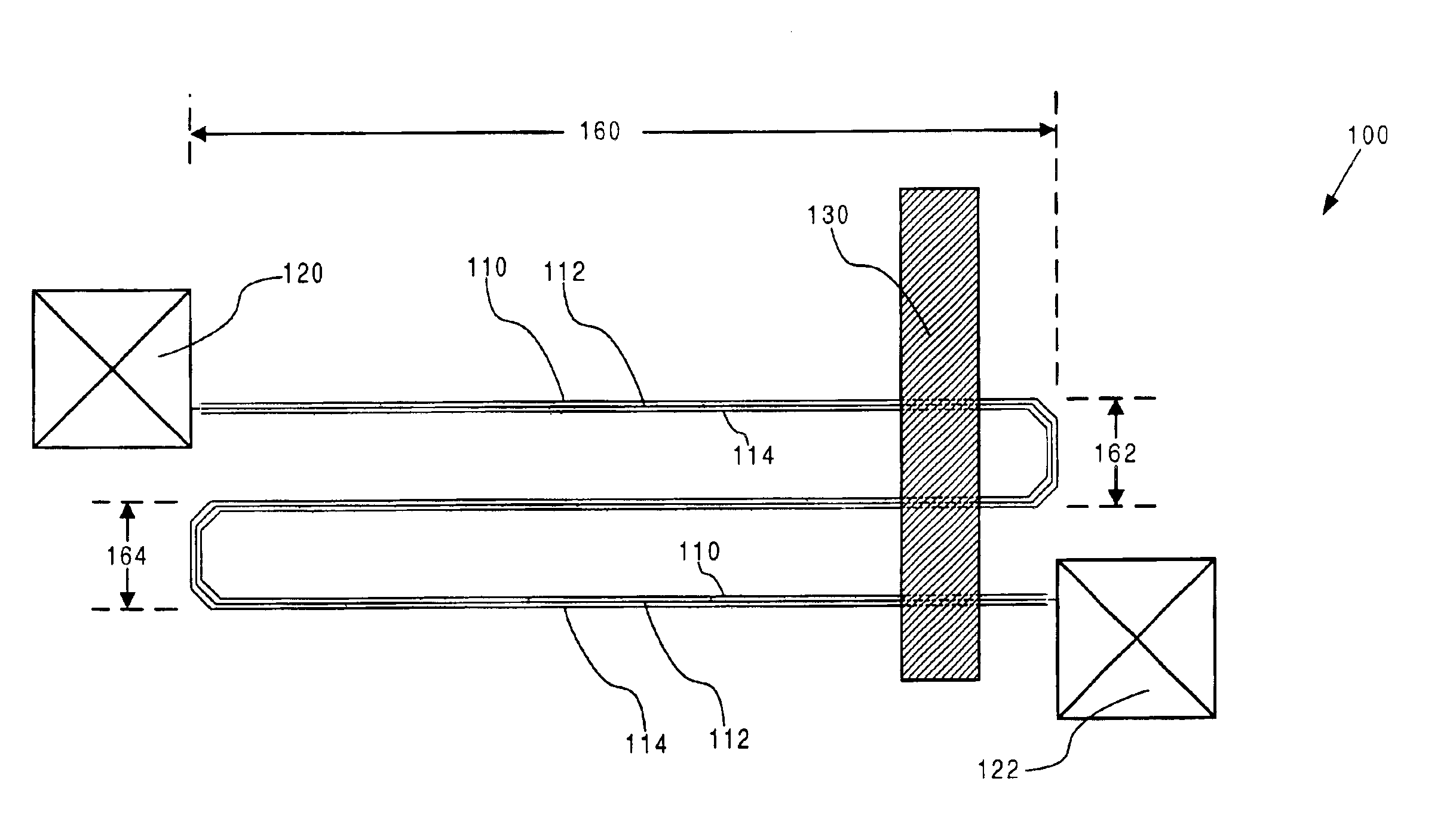
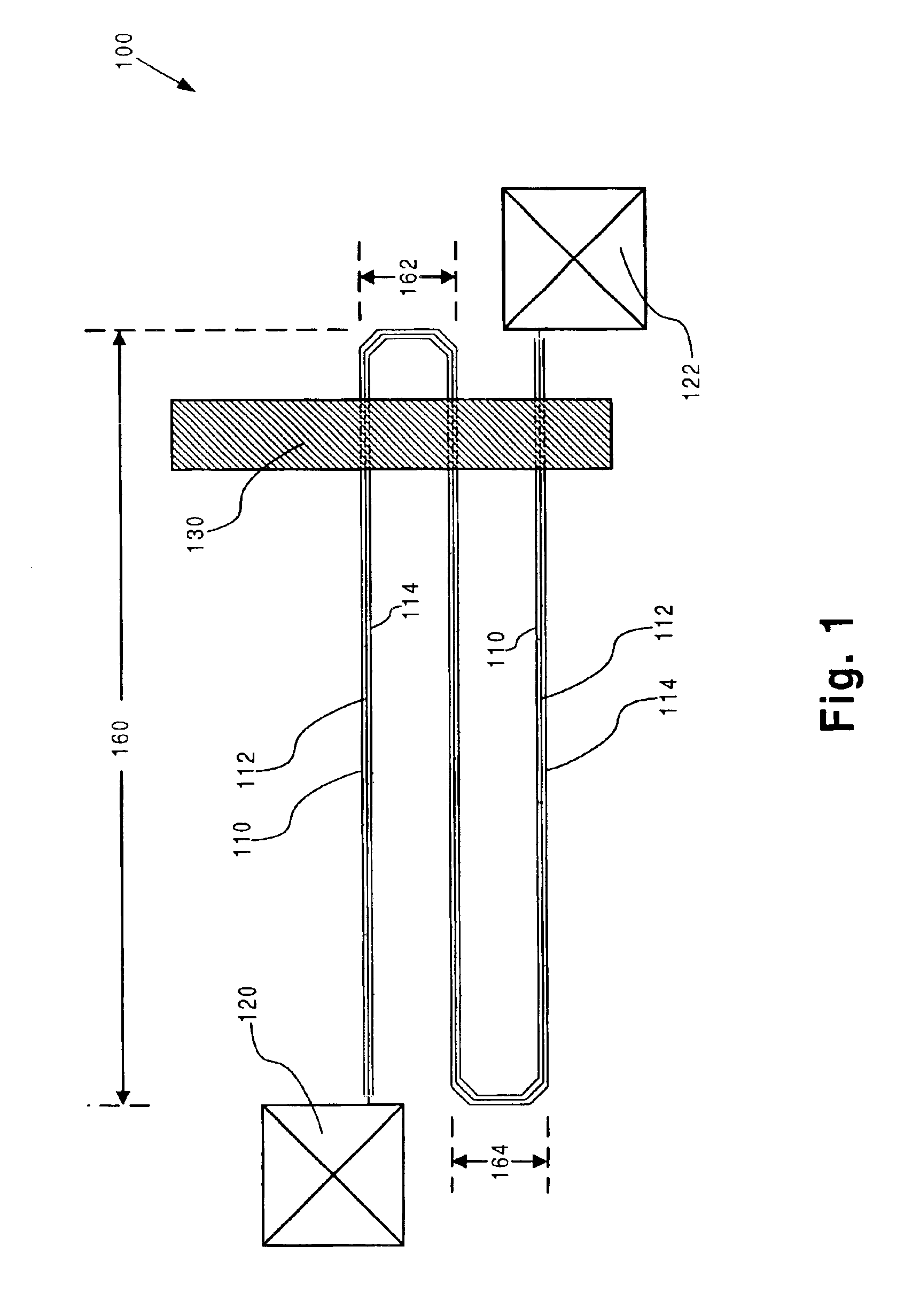
[0013]FIG. 1 shows a top view of test structure 100 formed in accordance with one embodiment of the invention. In one embodiment, test structure 100 is situated on a...


PUM


Abstract

A space-saving test structure includes a core metal line, at least one extrusion detection line and an extrusion monitoring segment. The core metal line has a “non-linear configuration” and is capable of conducting current for an electromigration test, an isothermal test, and extrusion monitoring. The at least one extrusion detection line is situated adjacent to the core metal line. The extrusion monitoring segment is electrically connected to the at least one extrusion detection line. The extrusion monitoring segment is adapted to determine whether an extrusion occurs in the core metal line by measuring a resistance between the core metal line and the at least one extrusion detection line.

Description

TECHNICAL FIELD[0001]The present invention relates generally to the field of semiconductor devices. More particularly, the present invention relates to test structures in semiconductor devices.BACKGROUND ART[0002]The lifetime, i.e. time between first use and failure, of semiconductor dies can be approximated by test structures. Electromigration (“EM”), i.e. the transport of atoms in metal due to the “electron wind” effect, can ultimately cause failure in semiconductor dies due to the formation of “voids”, i.e. open circuits, or “hillocks”, i.e. extrusions causing short circuits, in metal lines.[0003]EM test structures simulate the failure of devices due to the effects of electromigration. The National Institute of Standards and Technology (“NIST”) has proposed a standard of 800 microns for EM test structure length. Conventional EM test structures comprise metal lines in a linear configuration having an EM test structure length of 800 microns. These conventional EM test structures ar...

Claims


Application Information

Patent Timeline
IPC IPC(8): G01R31/28
CPCG01R31/2831G01R31/2858G01R31/2884
Inventor KIM, HYEON-SEAG
Owner ADVANCED MICRO DEVICES INC
Why Eureka
Try Eureka